Introduction
The Voswitch JK100 is an advanced overhead programmable switch panel power control system designed specifically for Jeep Wrangler JK and JKU models from 2007-2018. This system provides a streamlined solution for controlling various aftermarket accessories, offering a clean, factory-like appearance and robust functionality. It features eight programmable switches, multiple backlight color options, and an integrated low-voltage cut-off circuit to protect your vehicle's battery.
This manual provides essential information for the installation, operation, maintenance, and troubleshooting of your Voswitch JK100 system.
Package Contents
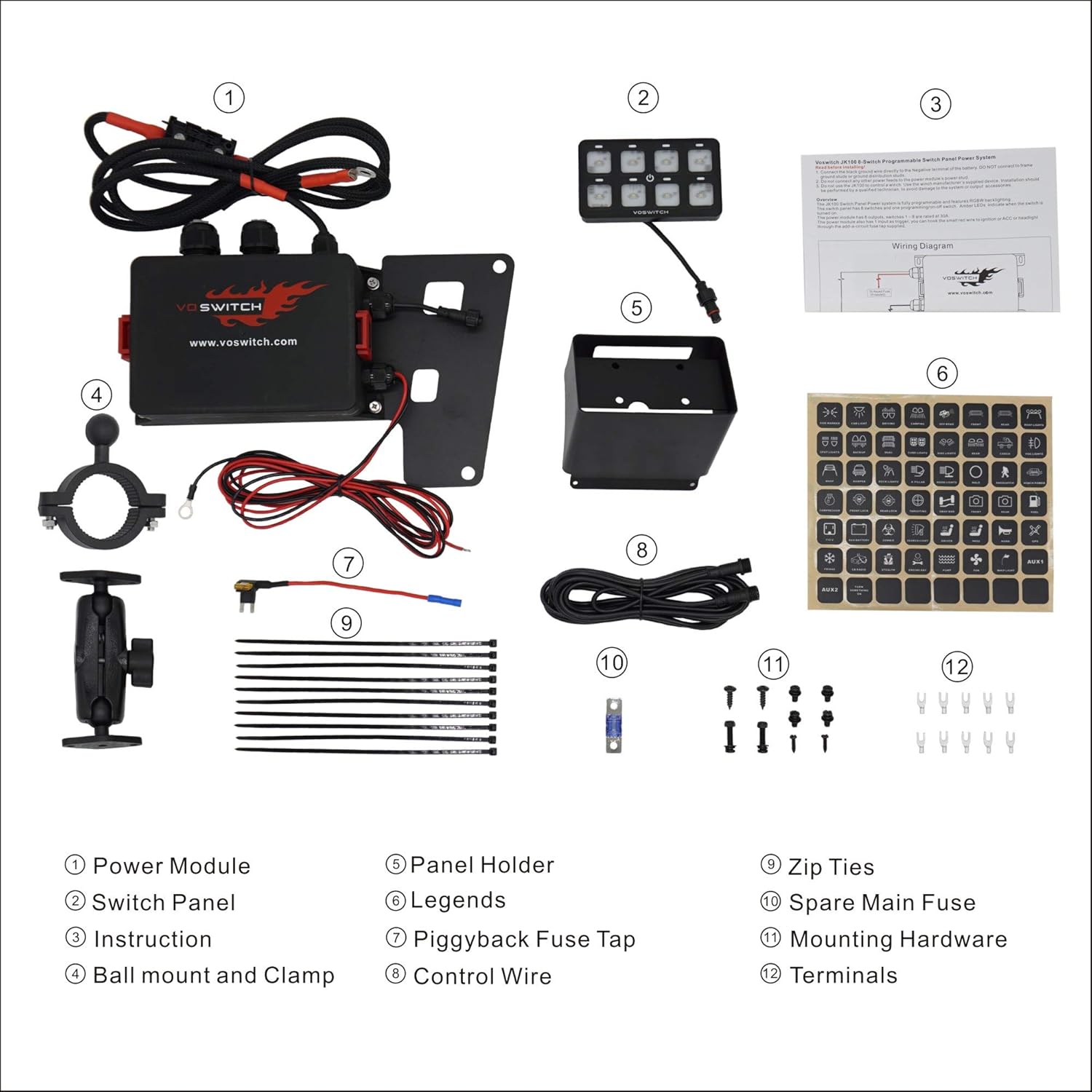
Figure 1: Voswitch JK100 Package Contents. This image displays all components included in the Voswitch JK100 system: 1) Power Module, 2) Switch Panel, 3) Instruction Manual, 4) Ball mount and Clamp, 5) Panel Holder, 6) Legends (switch labels), 7) Piggyback Fuse Tap, 8) Control Wire, 9) Zip Ties, 10) Spare Main Fuse, 11) Mounting Hardware, and 12) Terminals.
Before beginning installation, verify that all components listed below are present in your package:
- Power Module
- Switch Panel
- Instruction Manual (Printed)
- Ball Mount and Clamp
- Panel Holder
- Legends (Assorted Switch Labels)
- Piggyback Fuse Tap
- Control Wire
- Zip Ties
- Spare Main Fuse
- Mounting Hardware
- Terminals
Setup and Installation
The Voswitch JK100 system is designed for a straightforward, plug-and-play installation without the need for trimming or drilling in most applications. It is compatible with 12V battery systems.
Installation Steps Overview:
- Power Module Installation: Mount the waterproof power module in the engine bay. Ensure it is securely fastened and away from excessive heat or moving parts.
- Switch Panel Mounting: The switch panel can be installed overhead using the specific bracket designed for the Jeep Wrangler JK/JKU's footman loop, or via the included RAM mount for alternative locations.
- Wiring Connections: Connect the power module to the vehicle's 12V battery. Utilize the piggyback fuse tap for ignition-switched power if desired. Connect the control wire between the power module and the switch panel.
- Accessory Wiring: Connect your aftermarket accessories to the designated outputs on the power module. Ensure proper grounding for all accessories.
- Apply Legends: Select and apply the appropriate legends (labels) to each switch button on the panel to clearly identify the controlled accessory.

Figure 2: Power Module installed in the engine bay. The power module is designed to be mounted securely within the engine compartment, typically on the fender well or a similar stable surface.

Figure 3: Overhead switch panel installation using the specific bracket. This method allows for a clean, integrated look without modifications to the vehicle's interior.

Figure 4: Switch panel installed using a RAM mount. This provides flexibility for mounting the switch panel in various locations within the vehicle's cabin, such as on the A-pillar or dashboard.

Figure 5: Switch panel with various legends. The system includes a sheet of adhesive labels to customize each switch with an icon representing its function.
For detailed, step-by-step installation instructions, please refer to the official Installation Manual (PDF) provided with your product or available online.
Operating Instructions
The Voswitch JK100 features eight programmable switches, allowing for versatile control of your vehicle's accessories. Each switch can be configured for different operational modes and backlight colors.
Switch Operation Modes:
The system supports four distinct operation modes for each switch:
- Solid: The accessory remains on until the switch is pressed again.
- Flash: The accessory flashes on and off at a set interval.
- Strobe: The accessory strobes rapidly.
- Momentary: The accessory is active only while the switch is pressed and held.
Refer to the full instruction manual for detailed steps on how to program each switch to its desired mode.
Backlight Colors:
The switch panel offers four backlight color options to match your vehicle's dashboard lighting:
- Red
- Blue
- Green
- White
Instructions for changing backlight colors are provided in the comprehensive user manual.
Low-Voltage Cut-Off (LVCO):
The integrated LVCO circuit protects your vehicle's battery from excessive discharge. It will automatically cut off power to accessories if the battery voltage drops to 11.0VDC and will restore power when the voltage recovers to 12.4VDC. This ensures sufficient power remains to start your vehicle.
Maintenance
The Voswitch JK100 is designed for durability and low maintenance. The power module is waterproof, and the universal relays and fuses are replaceable, allowing for cost-effective maintenance.
- Regular Inspection: Periodically check all wiring connections for tightness and signs of wear or corrosion.
- Fuse Replacement: If an accessory stops working, check the corresponding fuse in the power module. Replace blown fuses with a fuse of the same amperage rating. A spare main fuse is included in the package.
- Cleaning: Clean the switch panel and power module exterior with a soft, damp cloth. Avoid using harsh chemicals or abrasive cleaners.
Troubleshooting
If you encounter issues with your Voswitch JK100 system, refer to the following common troubleshooting steps:
| Problem | Possible Cause | Solution |
|---|---|---|
| System does not power on. | No power from battery; Blown main fuse; Loose connections. | Check battery connections. Inspect and replace main fuse if blown. Ensure all power and ground wires are securely connected. |
| An accessory does not turn on. | Blown accessory fuse; Incorrect wiring to accessory; Faulty accessory. | Check the fuse for the specific accessory output on the power module. Verify accessory wiring. Test the accessory directly if possible. |
| Switch panel backlight is not working or incorrect color. | Programming error; Loose control wire connection. | Refer to the manual for backlight color programming. Check the connection of the control wire between the power module and switch panel. |
| System shuts off unexpectedly. | Low-Voltage Cut-Off (LVCO) activated. | Check vehicle battery voltage. Recharge or replace battery if necessary. Reduce accessory load if continuously triggering LVCO. |
If these steps do not resolve the issue, please contact Voswitch customer support for further assistance.
Specifications
| Feature | Detail |
|---|---|
| Model | JK100 |
| Operation Mode | ON-OFF (Programmable to Solid, Flash, Strobe, Momentary) |
| Current Rating | 30 Amps (per circuit, total 360 watts) |
| Operating Voltage | 12 Volts DC |
| Circuit Type | 8-way |
| Actuator Type | Push Button |
| Contact Material | Brass, Copper |
| International Protection Rating | IP54 (Power Module) |
| Control Method | Touch (for switch panel buttons) |
| Backlight Colors | Red, Blue, Green, White |
| Wattage | 360 watts (Total) |
| Low-Voltage Cut-Off (LVCO) | Cut-off at 11.0VDC, cuts-back in at 12.4VDC |
| Dimensions (Package) | 13.7 x 10.12 x 5.35 inches |
| Weight | 6.93 pounds |
Warranty and Support
Voswitch products are designed for reliability and performance. While specific warranty details are not provided in this manual, Voswitch is committed to customer satisfaction.
For technical support, troubleshooting assistance beyond what is covered in this manual, or warranty inquiries, please contact Voswitch customer service. You may find contact information on the official Voswitch website or through your point of purchase.
Online Resources:
- Official Installation Manual (PDF): https://manuals.plus/m/283faa322c4a85f82bcb9d6c8049a43cac97e854efc3af4da542fee99ef31ce3
- Voswitch Store on Amazon: https://www.amazon.com/stores/Voswitch/page/CBA29377-E1F8-489A-8EEB-38BF4510A4F7


