1. Introduction
This manual provides instructions for the installation, operation, and maintenance of your new HD Switch ignition key switch. This product is designed as a direct replacement for specific Dixon ZTR mower models, offering reliable starting and enhanced protection against environmental elements.
The HD Switch ignition key switch features a dual-layer protection system to safeguard against dirt and water ingress, promoting extended durability and consistent performance in demanding outdoor conditions.

Image 1.1: The HD Switch ignition key switch kit, including the switch unit, two keys, a mounting nut, and a protective cap.
2. Safety Information
Always observe the following safety precautions when working with electrical components and machinery:
- Disconnect Power: Before beginning any installation or maintenance, ensure the mower's battery is disconnected to prevent accidental starting or electrical shock.
- Consult Mower Manual: Refer to your Dixon ZTR mower's original instruction manual for specific wiring diagrams and safety procedures.
- Wear Protective Gear: Always wear appropriate personal protective equipment, such as safety glasses and gloves.
- Professional Installation: If you are unsure about any step of the installation process, it is recommended to seek assistance from a qualified technician.
- Avoid Forcing Components: Do not force the switch or keys. If resistance is encountered, re-evaluate the installation steps.
3. Package Contents
Verify that all items are present in your package:
- 1x HD Switch Ignition Key Switch Unit
- 2x HD Switch Keys (one with soft-grip umbrella design, one standard)
- 1x Mounting Nut
- 1x Protective Cap
- 1x Carabiner Keychain (for keys)

Image 3.1: Included components: two keys, mounting nut, and protective cap.
4. Setup and Installation
This section outlines the general procedure for replacing your mower's ignition switch. Specific wiring configurations may vary by mower model. Always refer to your mower's service manual for detailed wiring diagrams.
Tools Required:
- Wrench (appropriate size for mounting nut)
- Screwdriver (if needed to access the switch panel)
- Wire cutters/strippers (if wiring repair is necessary)
Installation Steps:
- Prepare the Mower: Ensure the mower is turned off, the parking brake is engaged, and the engine is cool. Disconnect the negative (-) terminal of the battery to prevent accidental electrical discharge.
- Access the Switch: Locate the existing ignition switch on your mower's control panel. You may need to remove a panel or cover to access the rear of the switch and its wiring.
- Document Wiring: Before disconnecting any wires, carefully note or photograph the existing wiring connections to the old switch. This is crucial for correct reinstallation.
- Remove Old Switch: Disconnect all wires from the terminals of the old switch. Then, unscrew the mounting nut holding the old switch in place and remove it from the panel.
- Install New Switch: Insert the new HD Switch ignition switch into the opening on the control panel. Ensure it is oriented correctly.
- Secure the Switch: Thread the provided mounting nut onto the switch from the front of the panel and tighten it securely with a wrench. Do not overtighten.
- Reconnect Wiring: Using your documented notes or photographs, carefully reconnect the wires to the corresponding terminals on the new HD Switch. Ensure all connections are secure.
- Install Protective Cap: Place the protective cap over the keyhole of the switch when the key is not inserted. This provides the dual-layer protection against dirt and water.
- Restore Power: Reinstall any covers or panels removed earlier. Reconnect the negative (-) terminal of the battery.
- Test Operation: Insert the key and test the switch's functionality according to the operating instructions in Section 5.

Image 4.1: The HD Switch unit, ready for installation.
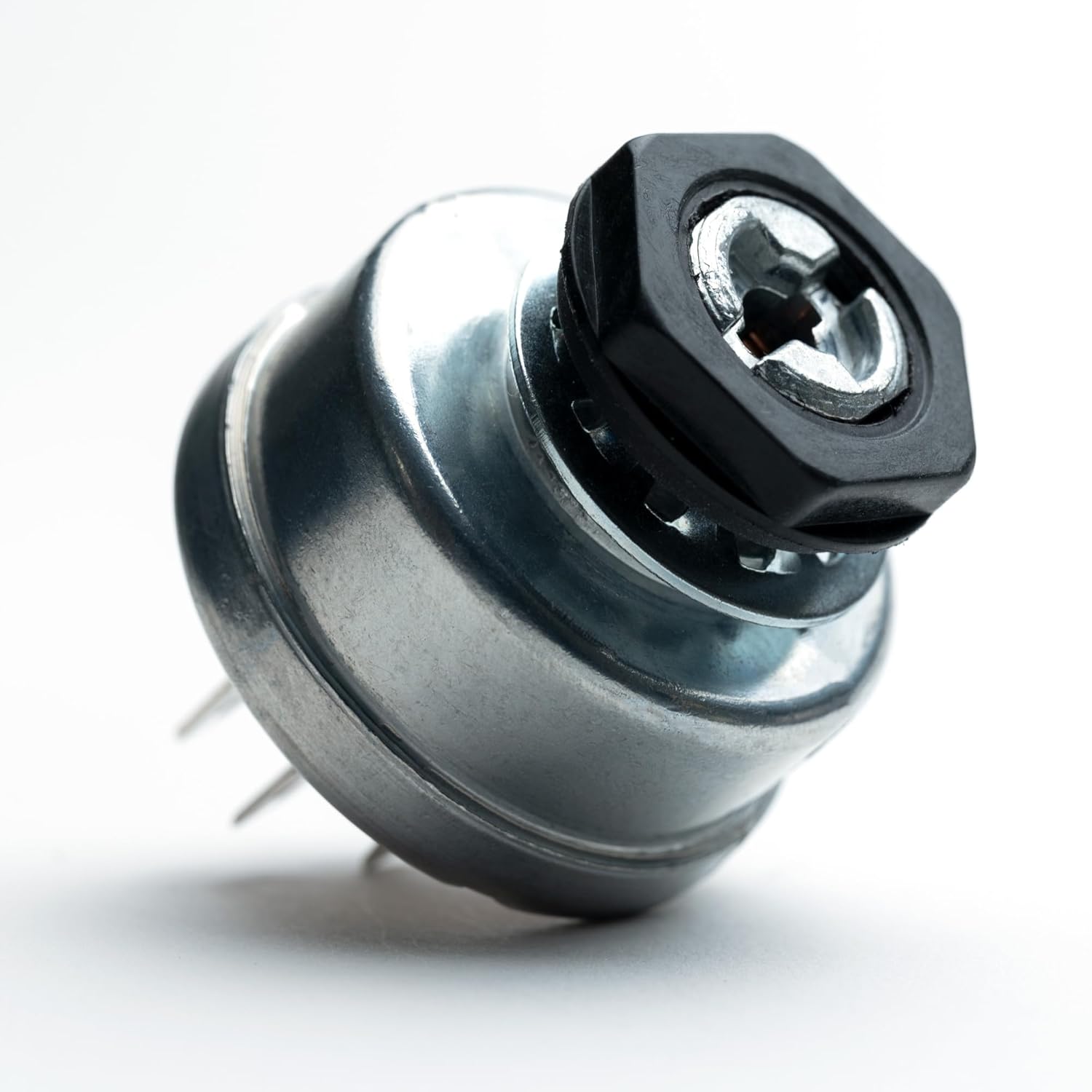
Image 4.2: The switch secured with its mounting nut.
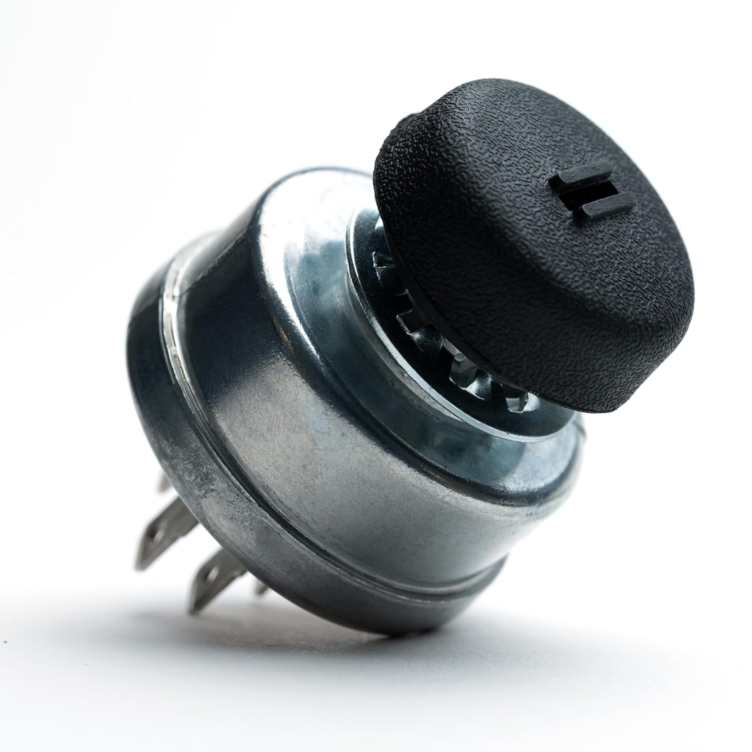
Image 4.3: The switch with the protective cap in place.
5. Operation
Operating the HD Switch ignition key switch is straightforward:
- Insert Key: Insert one of the provided HD Switch keys into the keyhole.
- Turn to ON: Rotate the key clockwise to the
Related Documents - ZTR3362, ZTR4421, ZTR4422, ZTR4423, ZTR4424, ZTR4425

Toyota 1NZ-FE Starting System and Starter Service Manual
Comprehensive service manual for Toyota 1NZ-FE engine starting system, detailing starter motor, relays (starter, ACC cut, integration, ignition), and ignition switch. Includes removal, inspection, and reassembly procedures.
John Deere X950R Lawn Tractor Replacement Parts Guide
Comprehensive replacement parts guide for the John Deere X950R Lawn Tractor, detailing essential components for the tractor and its 48-inch and 54-inch mower decks, including part numbers and specifications.
Electroair EA-23000 Installation Manual for Aircraft Ignition/Starter Switch Panel
This manual provides detailed installation instructions for the Electroair EA-23000 Ignition/Starter Switch Panel, designed for aircraft equipped with two electronic ignition systems. It covers kit contents, pre-installation checks, safety precautions, step-by-step installation procedures, and final testing.
Kayoba Marine Accessories Ignition Lock Operating Instructions
Operating and safety instructions for the Kayoba Marine Accessories ignition lock (model 650-446), featuring circuit diagrams and multilingual guidance.
John Deere Q820M Quik Trak Mower Replacement Parts Guide
Comprehensive replacement parts guide for the John Deere Q820M Quik Trak™ Mower, including engine, electrical, deck, and transmission components. Find part numbers and maintenance intervals for various deck sizes.
Carefree Mirage RV Awning Service Manual
This comprehensive service manual provides detailed instructions for the installation, maintenance, troubleshooting, and repair of the Carefree Mirage Patio Awning. It covers various models and systems, including standard and direct response electronics, and offers guidance on electrical wiring, motor replacement, and fabric care.

Image 5.1: The HD Switch key, designed for protection.