1. Introduction
The DIYmall ESP32 LoRa V3 WiFi+BLE Development Board is a versatile IoT development board. This V3 version integrates Wi-Fi, Bluetooth Low Energy (BLE), LoRa, and a 0.96-inch OLED display, offering a comprehensive solution for various embedded projects. It is designed for applications in smart cities, farms, homes, industrial control, security systems, wireless meter reading, and general IoT development.
Key Features:
- Integrated Connectivity: Features Wi-Fi, BLE, and LoRa for diverse communication needs.
- Onboard Display: Includes a 0.96-inch OLED display for direct feedback and information.
- Enhanced Performance: Utilizes ESP32-S3FN8 MCU and SX1262 LoRa chip for improved capabilities over previous versions.
- Modern Interface: Equipped with a Type-C USB socket for convenient power and data transfer.
- Optimized RF: Upgraded V3 version features better impedance matching of RF circuits for reliable performance.
- Development Friendly: Supports multiple development methods including Arduino, MicroPython, Platform.io, and Espressif IDE.
2. Product Overview
2.1. Components and Interfaces
The DIYmall ESP32 LoRa V3 board includes several key components and interfaces for development and operation.

2.2. Version Comparison (V2 vs. V3)
The V3 version introduces several upgrades compared to the previous WiFi LoRa 32 (V2) model.

| Item | WiFi LoRa 32 (V2) | WiFi LoRa 32 (V3) |
|---|---|---|
| MCU | ESP32-D0 | ESP32-S3FN8 |
| LoRa Chip | SX1276/8 | SX1262 |
| USB Socket | Micro-USB | Type-C |
| Crystal Oscillator | Ordinary crystal oscillator | High precision temperature compensated crystal oscillator |
| Low Power Features in Deep Sleep | ≈800uA | <10uA |
| Other Update | Better impedance matching of RF circuits |
Note: Due to the different MCUs, the GPIO pin definitions for V2 and V3 are not compatible.
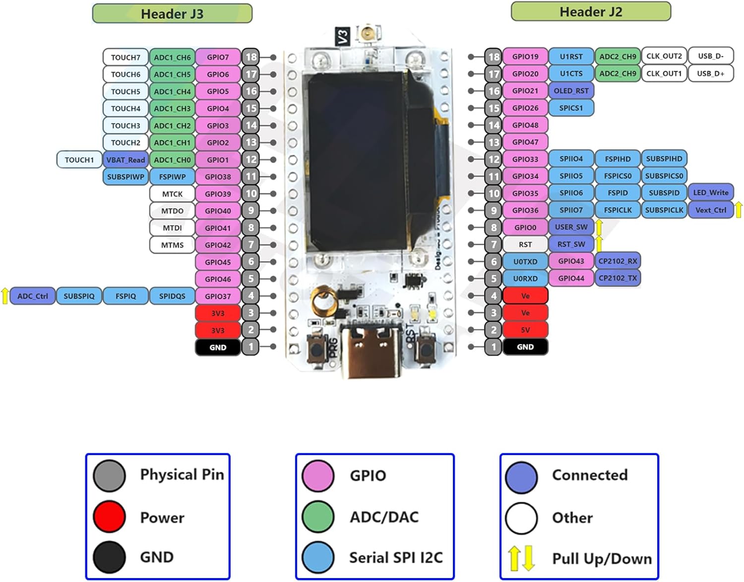
2.3. Pin Map
3. Setup
3.1. Initial Assembly
The ESP32 LoRa V3 development board comes with an antenna and optional protective case. Ensure the antenna is securely connected to the IPEX1.0 connector on the board.

For battery operation, connect a lithium battery to the SH1.25-2 interface. The board supports charging of the lithium battery when connected via USB or the 5V pin.
3.2. Software Setup (Arduino IDE)
The recommended development environment is Arduino IDE. Follow these steps for initial setup:
- Install Arduino IDE: Download and install the latest version of Arduino IDE from the official website.
- Install ESP32 Boards Package:
- Open Arduino IDE, go to
File > Preferences. - In the 'Additional Boards Manager URLs' field, add the Heltec ESP32 JSON URL:
https://resource.heltec.cn/download/package_heltec_esp32_index.json - Go to
Tools > Board > Boards Manager.... - Search for 'ESP32' and install the 'ESP32 by Espressif Systems' package.
- Search for 'heltec esp32' and install the 'Heltec ESP32 Series Dev-boards' package.
- Open Arduino IDE, go to
- Install Required Libraries:
- Go to
Sketch > Include Library > Manage Libraries.... - Search for 'Adafruit GFX Library' and install it. When prompted for dependencies, click 'Install All'.
- Download the 'Robojax Heltec LoRa 32' library (usually a .zip file) from the provided resources.
- In Arduino IDE, go to
Sketch > Include Library > Add .ZIP Library...and select the downloaded .zip file.
- Go to
- Select Board and Port:
- Connect your ESP32 LoRa V3 board to your computer via a Type-C USB cable.
- Go to
Tools > Board > Heltec ESP32 Series Dev-boards > Heltec WiFi LoRa 32(V3). - Go to
Tools > Portand select the COM port corresponding to your connected board.
3.3. Firmware Flashing (Meshtastic)
For Meshtastic functionality, you can flash the firmware using the Meshtastic Web Flasher.
- Visit the Meshtastic Web Flasher website.
- Select 'Heltec V3' as your device.
- Choose the desired firmware version (stable or alpha).
- Ensure your device is plugged in via USB. You may need to turn off, press and hold the BOOT / PRG button while plugging in the USB cable.
- Choose the baud rate (115200 is standard).
- Click 'Erase Flash and Install' to flash the firmware.
4. Operating Instructions
4.1. LoRa Communication (Sender/Receiver)
The ESP32 LoRa V3 boards can be configured as a sender (TX) and a receiver (RX) for LoRa communication. You will need two boards for this functionality.
When using the ESP32 LoRa V3 for communication, one board acts as a sender (TX) and the other as a receiver (RX). Ensure both boards are configured with matching LoRa frequency, bandwidth, spreading factor, and coding rate for successful communication.
4.2. Door Monitoring Project Example
The ESP32 LoRa V3 can be used for various IoT projects, such as a door monitoring system. This involves connecting a Hall Effect sensor to one board (transmitter) and a relay or buzzer to another board (receiver).
When the magnet (attached to the door) moves away from the Hall Effect sensor, the transmitter board sends an 'OPEN' signal. The receiver board then activates a connected device (e.g., a buzzer or a relay to control a light) and displays 'OPEN' on its OLED screen. When the magnet is close to the sensor, a 'CLOSED' signal is sent, deactivating the connected device and displaying 'CLOSED'.
5. Maintenance
5.1. Power Supply and Battery
The board can be powered via the Type-C USB port, the 5V pin, or a connected lithium battery. When using a lithium battery, ensure it is connected correctly to the SH1.25-2 interface. The board supports charging of the lithium battery when powered via USB or the 5V pin. In other cases, only a single power supply can be connected.
| Power Supply Mode | Minimum (V) | Typical (V) | Maximum (V) | Current (mA) |
|---|---|---|---|---|
| Type-C USB | 4.7 | 5 | 6 | ≥500 |
| Lithium battery | 3.3 | 3.7 | 4.2 | ≥250 |
| 5V pin | 4.7 | 5 | 6 | ≥500 |
| 3V3 pin | 2.7 | 3.3 | 3.5 | ≥150 |
6. Troubleshooting
6.1. Meshtastic Screen Digital Front-End Issue
If you encounter a digital front-end issue with the Meshtastic screen, it is typically caused by the Meshtastic settings. This can be resolved by changing the default screen to SSD1306.
Steps to resolve:
- Navigate to 'Radio configuration' in Meshtastic settings.
- Select 'Display'.
- Choose 'Override OLED auto-detect'.
- Select 'SSD1306'.
6.2. V2 Code Compatibility with V3
No, V2 code is not compatible with V3 due to the difference in the Microcontroller Unit (MCU).
7. Specifications
| Feature | Detail |
|---|---|
| Model Number | FZ2886-AX2K |
| MCU | ESP32-S3FN8 |
| LoRa Chip | SX1262 |
| Wireless Type | 802.11bgn, Bluetooth |
| OLED Display | 0.96 inch |
| USB Socket | Type-C |
| RAM | LPDDR4 (32 MB installed) |
| Processor Brand | Espressif |
| Number of Processors | 2 |
| CPU Speed | 0.24 GHz |
| Operating System | FreeRTOS |
| Item Weight | 3.2 ounces |
| Product Dimensions | 1.97 x 1 x 0.38 inches |
| Manufacturer | Heltec Automation Technology Co., Ltd |
8. Support
For further assistance, technical support, or inquiries regarding your DIYmall ESP32 LoRa V3 Development Board, please contact the seller directly through the platform where the product was purchased.

