1. Introduction
The TEMPO PA1574 Network Cable Tester is a professional-grade tool designed for quick and accurate testing of Ethernet and telecom cables. It verifies continuity and correct wiring for RJ45, RJ11, RJ12, CAT5E, and CAT6 cables, identifying common wiring faults such as opens, shorts, and cross-connections. This manual provides detailed instructions for the proper setup, operation, and maintenance of your PA1574 cable tester.
2. Safety Information
- Do Not Use on Live Circuits: This device is not designed for testing cables connected to active network equipment or power sources. Doing so may damage the tester and connected equipment, and poses an electrical hazard.
- Battery Safety: Use only the specified 9V battery. Ensure correct polarity during installation. Remove the battery if the unit will not be used for an extended period to prevent leakage.
- Environmental Conditions: Operate and store the tester within specified temperature and humidity ranges. Avoid exposure to extreme temperatures, moisture, or corrosive environments.
- Maintenance: Do not attempt to open or repair the unit. Refer all servicing to qualified personnel.
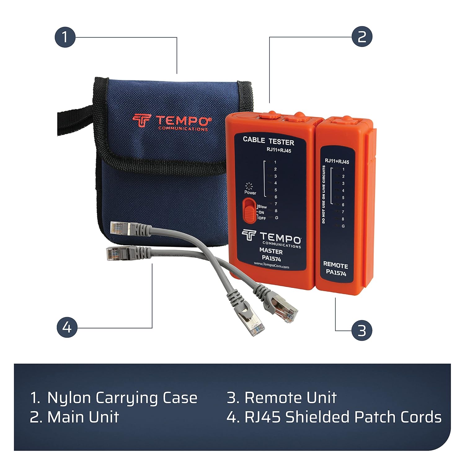
3. Package Contents
Verify that all items are present in your package:
- TEMPO PA1574 Master Unit
- TEMPO PA1574 Remote Unit
- 2 x RJ45 Patch Cords
- 1 x 9V Battery (pre-installed or included separately)
- Durable Nylon Carrying Case with Belt Loop

4. Product Overview
The TEMPO PA1574 consists of two main parts: a Master Unit and a Remote Unit. Both units feature LED indicators for each wire pair (1-8) and a ground (G) connection, allowing for comprehensive testing of cable integrity. A three-position slide switch controls power and scan speed.
Key Features:
- Quick Cable Testing: Efficiently checks Ethernet and telecom cables for continuity and correct wiring.
- Automatic Scanning: Initiates scanning automatically when cables are connected and the unit is powered on.
- Versatile Usage: Compatible with RJ45, RJ11, RJ12, and RJ14 connectors, supporting CAT5E and CAT6 standards. Suitable for testing patch cords and installed building wiring.
- Long Cable Testing: Capable of testing cables up to 1,650 feet (500 meters).
- Portability: Includes a durable nylon carrying case for easy transport and storage.


5. Setup
5.1. Battery Installation
The TEMPO PA1574 requires one 9V battery. The battery compartment is located on the back of the Master Unit. Ensure the battery is installed with the correct polarity. A fresh battery is included with your purchase.
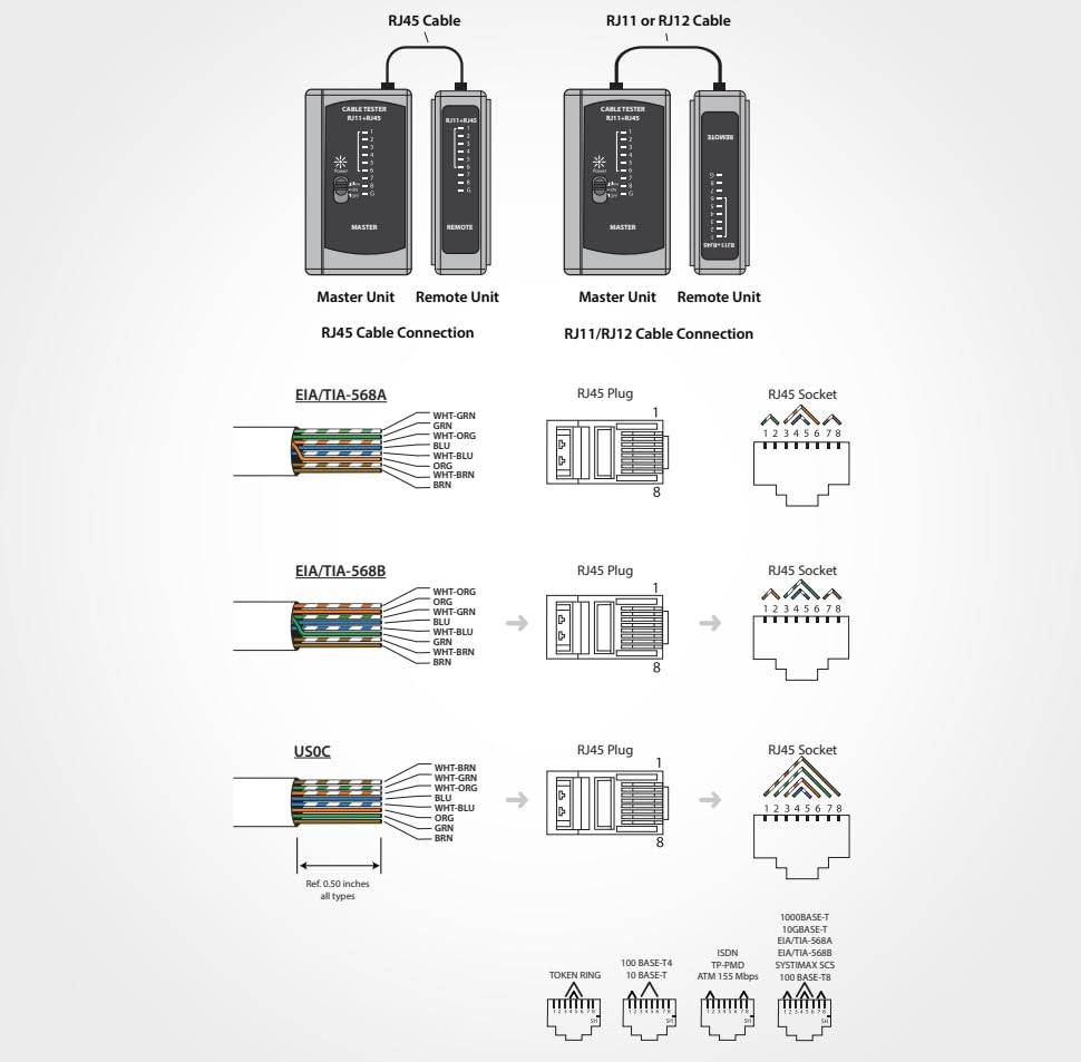
5.2. Connecting the Units
For testing patch cords, the Master Unit and Remote Unit can be connected directly to each other via a short patch cable or by inserting the cable ends into their respective ports. For installed wiring, the Master Unit remains at one end of the cable run, and the Remote Unit is placed at the other end.
6. Operation
6.1. Powering On and Off
Locate the three-position slide switch on the Master Unit:
- ON: Powers on the unit and initiates a normal-speed scan.
- SLOW: Powers on the unit and initiates a slower scan, useful for detailed observation of LED sequences.
- OFF: Powers off the unit.
6.2. Testing RJ45 Cables (CAT5E, CAT6)
- Ensure the cable to be tested is disconnected from all network devices and power sources.
- Insert one end of the RJ45 cable into the RJ45 port on the Master Unit.
- Insert the other end of the RJ45 cable into the RJ45 port on the Remote Unit.
- Slide the power switch on the Master Unit to either ON or SLOW.
- Observe the LED sequence on both the Master and Remote Units.


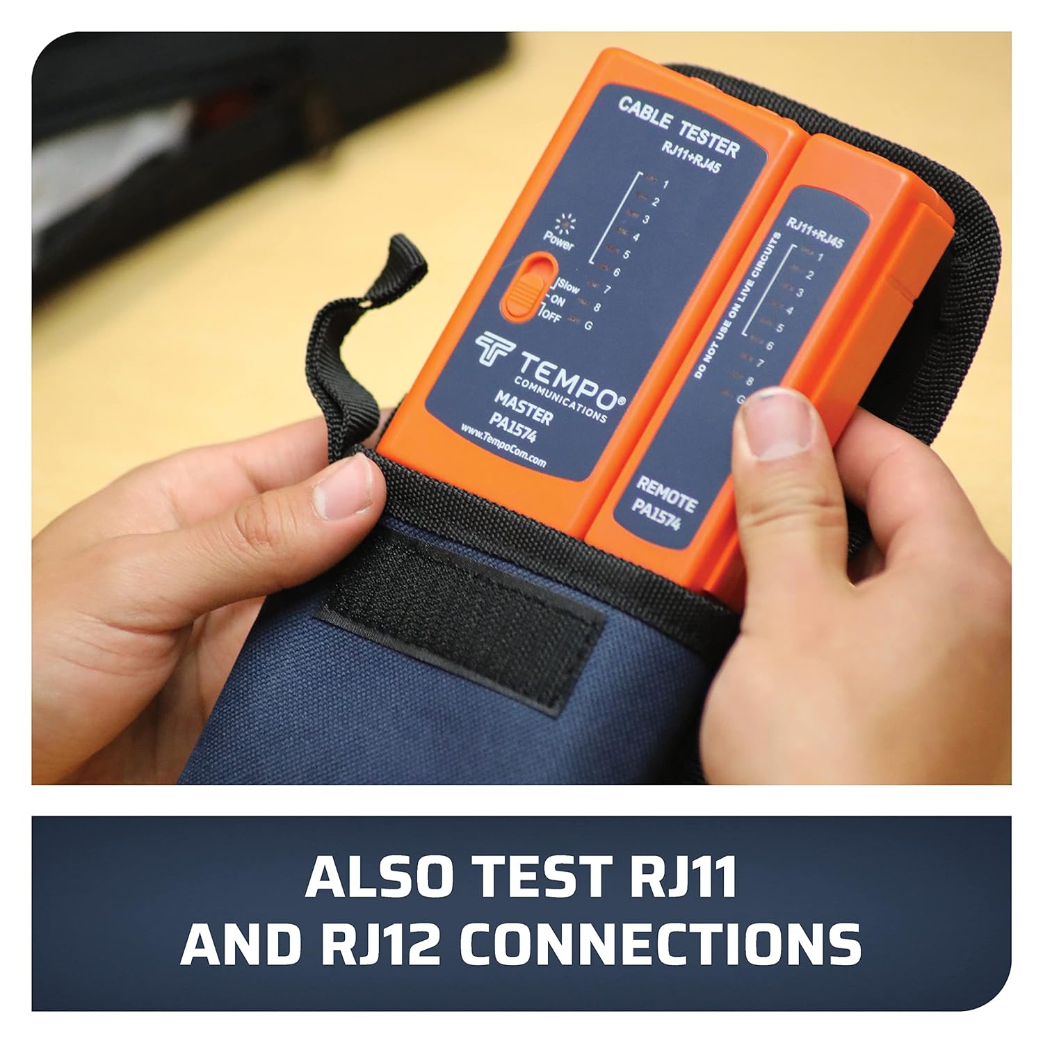
6.3. Testing RJ11, RJ12, RJ14 Cables
- Ensure the cable is disconnected from all devices.
- Insert one end of the RJ11/RJ12/RJ14 cable into the corresponding port on the Master Unit.
- Insert the other end of the cable into the corresponding port on the Remote Unit.
- Slide the power switch on the Master Unit to ON or SLOW.
- Observe the LED sequence. The tester will illuminate LEDs corresponding to the active pins for RJ11 (2-wire), RJ12 (4-wire), or RJ14 (6-wire) configurations.
7. Interpreting Test Results
The PA1574 uses a sequence of LEDs (1-8 and G for Ground) on both the Master and Remote units to indicate the wiring status. A normal, correctly wired cable will show the LEDs illuminating in sequence (1-2-3-4-5-6-7-8-G) on both units simultaneously.
Common Faults and LED Indications:
- Open Circuit (Broken Wire): If an LED on either the Master or Remote Unit does not light up in sequence, it indicates an open circuit (a broken wire) for that specific pin. For example, if LED 3 on both units fails to light, wire 3 is open.
- Short Circuit: If two or more LEDs light up simultaneously on either unit, it indicates a short circuit between those wires. For example, if LEDs 1 and 2 light up together, wires 1 and 2 are shorted.
- Cross-Connection (Split Pair/Reversed Pair): If the LED sequence on the Remote Unit does not match the sequence on the Master Unit, it indicates a cross-connection or reversed pair. For example, if Master LED 1 lights up, but Remote LED 2 lights up, there is a cross-connection between pins 1 and 2.
- No Lights: If no LEDs light up, check the battery, ensure the unit is powered on, and verify that the cable is properly seated in both ports.
8. Maintenance
8.1. Cleaning
Wipe the unit with a soft, dry cloth. Do not use abrasive cleaners or solvents. Keep the connector ports free of dust and debris.
8.2. Battery Replacement
When the LEDs become dim or the unit fails to power on, replace the 9V battery. Open the battery compartment cover on the back of the Master Unit, remove the old battery, and insert a new 9V alkaline battery, observing correct polarity. Securely close the cover.
8.3. Storage
Store the cable tester in its nylon carrying case in a cool, dry place away from direct sunlight and extreme temperatures. Remove the battery if storing for extended periods (more than one month) to prevent potential battery leakage and damage to the unit.
9. Troubleshooting
| Problem | Possible Cause | Solution |
|---|---|---|
| Tester does not power on. | Dead or improperly installed 9V battery. | Replace the 9V battery, ensuring correct polarity. |
| No LEDs light up during a test. | Cable not properly connected; severe cable fault (e.g., all wires open); battery low. | Ensure cable ends are fully inserted. Check battery. Test with a known good cable. |
| Incorrect LED sequence or unexpected lights. | Cable fault (open, short, cross-connection). | Refer to Section 7, "Interpreting Test Results," for detailed fault identification. Re-terminate or replace the cable if necessary. |
| LEDs are dim. | Low battery. | Replace the 9V battery. |
10. Specifications
- Model: PA1574
- Supported Cable Types: RJ45 (CAT5E, CAT6), RJ11, RJ12, RJ14
- Maximum Cable Length: 1,650 feet (500 meters)
- Power Source: 1 x 9V Battery (included)
- Dimensions (Package): 7.44 x 5.55 x 2.8 inches
- Weight (Package): 10.23 ounces
- Manufacturer: Tempo Communications
- Color: Orange
11. Warranty and Support
The TEMPO PA1574 Network Cable Tester is manufactured by Tempo Communications. For specific warranty details, please refer to the warranty card included with your product or visit the official Tempo Communications website. Tempo Communications is committed to providing reliable tools and support for technicians.
Optional protection plans may be available for extended coverage. Please check with your retailer for details on available plans.
For technical support, product information, or service inquiries, please contact Tempo Communications directly through their official website or customer service channels.


