1. Introduction
This manual provides detailed instructions for the proper use and maintenance of your Mcbazel Surecom SW-114 SWR RF Field Strength Test Meter. This device is designed to assist in the setup and optimization of CB radio systems by measuring Standing Wave Ratio (SWR), RF power, and relative field strength. Please read this manual thoroughly before operation to ensure safe and effective use.
2. Safety Information
- Ensure all connections are secure before applying power to your radio equipment.
- Do not exceed the maximum power ratings of the device (100W).
- Operate the meter in a dry environment. Avoid exposure to moisture or extreme temperatures.
- This device is intended for CB band (27-30MHz) operation only. Do not use for VHF/UHF frequencies.
- Keep the device away from strong magnetic fields.
3. Package Contents
Verify that all items are present in your package:
- 1x Surecom SW-114 SWR/Power Meter
- 1x Field Strength Antenna
- 1x English User Manual
Note: Coaxial cables and connectors are not included and must be purchased separately.

Figure 3.1: Contents of the SW-114 package.
4. Product Overview
The Surecom SW-114 features two analog meters for SWR/RF power and field strength, along with switches for power range and direction.

Figure 4.1: Front view of the SW-114 meter with key components labeled.
4.1. Controls and Indicators
- WATT Meter: Displays RF power (Forward/Reflected) and SWR.
- SWR Meter: Displays SWR and relative field strength (F.S.).
- 10W/100W Switch: Selects the power range for RF power measurements.
- FWD/REF Switch: Selects between Forward (FWD) and Reflected (REF) power measurements.
- TX Connector (SO-239): Connects to the transceiver (radio).
- ANT Connector (SO-239): Connects to the antenna system.
- Field Strength Antenna Port: For connecting the included field strength antenna.
- SET Knob: Used for SWR calibration.
5. Setup
Follow these steps to connect your SW-114 meter to your CB radio system:
- Connect Transceiver: Using a suitable coaxial cable (not included), connect the output of your CB transceiver to the TX connector on the SW-114 meter.
- Connect Antenna: Using another suitable coaxial cable (not included), connect your antenna system to the ANT connector on the SW-114 meter.
- Install Field Strength Antenna: If you intend to measure field strength, screw the provided field strength antenna into its dedicated port on the side of the meter.

Figure 5.1: Connection points on the SW-114 meter.
6. Operating Instructions
6.1. Measuring SWR (Standing Wave Ratio)
SWR measurement is crucial for ensuring your antenna system is efficiently transmitting power.
- Set the 10W/100W switch to the appropriate power range for your transceiver (e.g., 10W for lower power, 100W for higher power).
- Set the FWD/REF switch to FWD (Forward).
- Key your transceiver (transmit a continuous carrier, typically by pressing the PTT button without speaking). Observe the needle on the WATT meter.
- While still keying the transceiver, adjust the SET knob until the needle on the SWR meter aligns with the "SET" mark (usually at the far right of the scale).
- Release the PTT button.
- Set the FWD/REF switch to REF (Reflected).
- Key your transceiver again. The needle on the SWR meter will now indicate the SWR value. An SWR of 1.5:1 or lower is generally considered good.
- Release the PTT button.
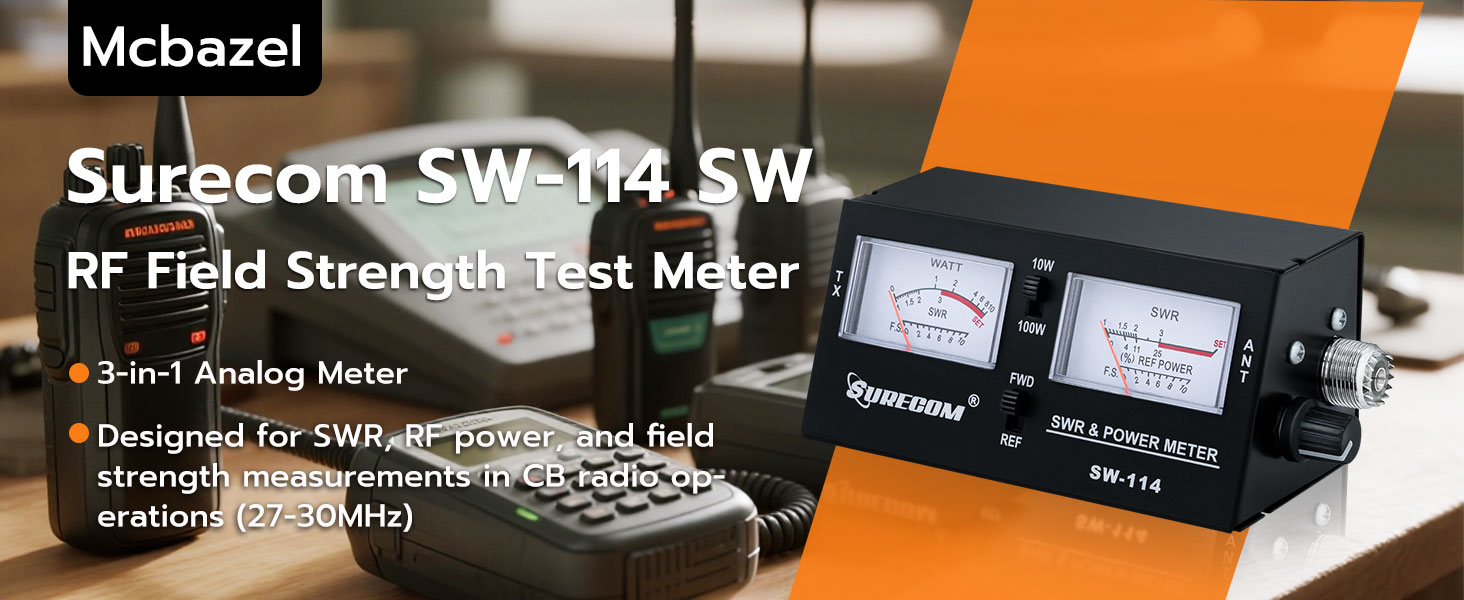
Figure 6.1: SWR measurement process.
6.2. Measuring RF Power
The meter can measure both forward and reflected RF power.
- Set the 10W/100W switch to the desired power range.
- Set the FWD/REF switch to FWD to measure forward power.
- Key your transceiver. The WATT meter will display the forward RF power in watts.
- To measure reflected power, set the FWD/REF switch to REF and key your transceiver. The WATT meter will display the reflected RF power.
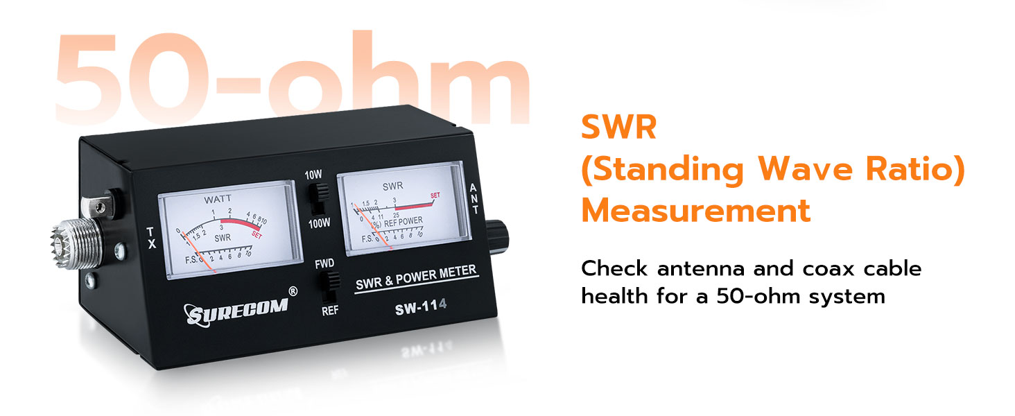
Figure 6.2: RF Power measurement using FWD/REF switches.
6.3. Measuring Field Strength
Field strength measurement helps assess the signal radiation from your antenna.
- Ensure the field strength antenna is properly installed in its port.
- Set the FWD/REF switch to FWD.
- Key your transceiver. The SWR meter will display the relative field strength (F.S.) on its lower scale.
- Move the meter around the antenna to observe variations in signal strength. Higher readings indicate stronger signal radiation.

Figure 6.3: Field strength measurement using the dedicated antenna.
7. Maintenance
- Keep the device clean and free from dust. Use a soft, dry cloth for cleaning.
- Avoid dropping the meter or subjecting it to strong impacts.
- Store the meter in a cool, dry place when not in use.
- Do not attempt to open the casing or modify the internal components, as this will void any potential warranty and may damage the device.
8. Troubleshooting
| Problem | Possible Cause | Solution |
|---|---|---|
| No meter deflection when transmitting. |
|
|
| SWR reading is very high. |
|
|
| Field strength reading is low or absent. |
|
|
9. Specifications
| Feature | Detail |
|---|---|
| Model | SW-114 |
| Frequency Range | 27-30 MHz (CB Band) |
| Impedance | 50 Ohms |
| Power Range | 10W / 100W (selectable) |
| Functions | SWR, RF Power (Forward/Reflected), Field Strength |
| Connectors | SO-239 UHF Type |
| Product Dimensions (L x W x H) | 6.5 x 3.15 x 3.15 inches |
| Weight | 11.68 ounces |
| Power Source | Battery Powered (details not specified, typically internal or standard small battery) |
10. Warranty and Support
Mcbazel products are designed for reliability and performance. For warranty information, technical support, or service inquiries, please refer to the contact information provided with your purchase documentation or visit the official Mcbazel website. Please retain your proof of purchase for warranty claims.
For additional resources and product information, you may visit the Mcbazel Store on Amazon.


