1. Introduction
This manual provides essential instructions for the installation, operation, and maintenance of the FAS Liftmaster LA500PKGU Replacement Control Board, model K1D8388-1CC. This control board is designed as a genuine replacement part for specific Liftmaster gate operators, ensuring proper functionality and compatibility. Please read this manual thoroughly before proceeding with installation or operation.
2. Product Overview
The Liftmaster LA500PKGU Replacement Control Board (K1D8388-1CC) is a critical component for the reliable operation of compatible Liftmaster gate operators. This burgundy-colored Generation 3 control board manages various functions, including gate movement, safety features, and communication with accessories. It features multiple connectors for power, motor control, safety devices, and diagnostic indicators.
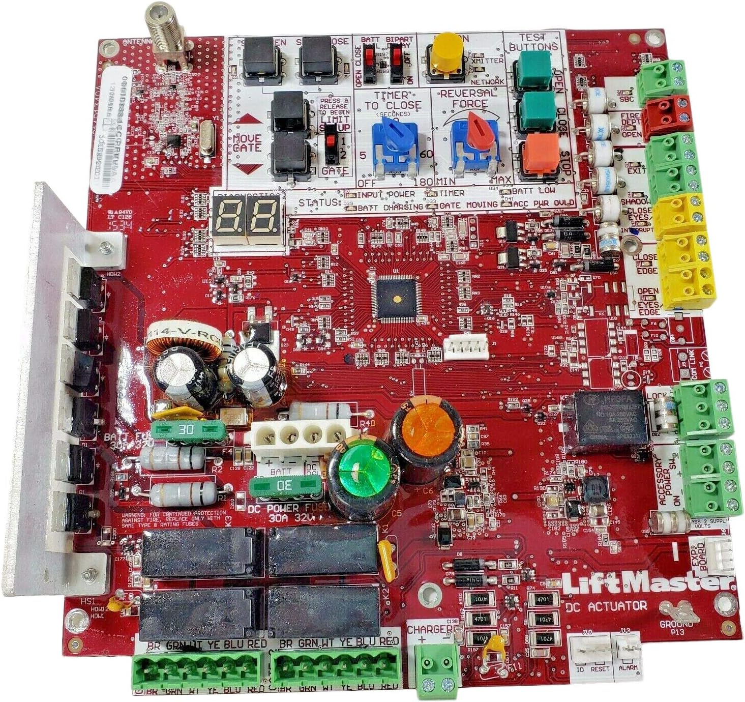
Figure 2.1: An overhead view of the red Liftmaster LA500PKGU Replacement Control Board, showing various components including connectors, fuses, capacitors, relays, and a diagnostic display. The board features clearly labeled terminals for power, gate control, and accessories.
3. Compatibility
This replacement control board is specifically designed for compatibility with the following Liftmaster gate operator models:
- LA400
- LA412
- LA500
Important Compatibility Notes:
- This Burgundy colored Generation 3 Control Board was introduced in January 2016.
- It is compatible with LA400, LA412, and LA500 gate operators manufactured after January 2016.
- This board is not compatible with gate operators manufactured before January 2016.
- The board is MYQ Compatible.
- Always check your individual equipment for compatibility before installation.
4. Safety Information
Always prioritize safety when working with electrical components and gate operators. Improper installation or maintenance can lead to serious injury or damage to equipment. It is highly recommended that installation and service be performed by a qualified technician.
- Disconnect Power: Always disconnect all power sources (AC and battery) to the gate operator before performing any work on the control board or associated wiring.
- Static Discharge: Handle the control board by its edges to avoid damage from electrostatic discharge.
- Fuse Replacement: For continued protection against fire, replace fuses only with the same type and rating. The DC Power Fuse is 30A 32V.
- Wiring: Ensure all wiring connections are secure and correctly matched according to the gate operator's wiring diagram.
5. Installation Instructions
This section outlines the general steps for replacing the control board. Refer to your specific gate operator's manual for detailed wiring diagrams and model-specific instructions.
- Prepare for Installation:
- Ensure all power to the gate operator is disconnected, including AC power and battery backup.
- Take clear photographs of the existing wiring connections on the old control board for reference.
- Label all wires before disconnecting them to ensure correct re-connection.
- Remove Old Control Board:
- Carefully disconnect all wires and connectors from the old control board.
- Unmount the old control board from its housing.
- Install New Control Board:
- Mount the new LA500PKGU Replacement Control Board securely in the designated position.
- Reconnect all wires and connectors to their corresponding terminals on the new board, using your photographs and labels as a guide. Pay close attention to the Main Power Connector (24-Pin).
- Ensure the external antenna is not grounding out on a fence or other metal object.
- Photo Eye Compatibility (Important):
- This Generation 3 board requires a Liftmaster brand photo eye entrapment device for proper diagnostic data exchange.
- If replacing an older board and using an older or aftermarket photo eye (NC NO type), it may issue an error code 60 (no entrapment device connected).
- To resolve this, an 8.2K resistor can be added across the Normally Open contact and common of the photo eye. The new board expects either a short or 8.2K ohms.
- Aftermarket photo sensors can be used as secondary devices.
- Power Up and Test:
- Once all connections are verified, restore battery power, then AC power to the gate operator.
- Observe the diagnostic display (e.g., "8.8." on the board) for any error codes.
- Perform initial setup and limit programming as per your gate operator's manual.
- Test all safety devices (photo eyes, reversal force) to ensure they function correctly.
6. Operation
The control board facilitates the automated operation of your gate operator. After successful installation and initial setup, the gate operator can be controlled via various methods, including remote transmitters, keypads, and other access control devices.
- Diagnostic Display: The integrated diagnostic display provides status information (e.g., "STATUS: BATT CHARGING", "GATE MOVING", "ACC PWR OULD") and error codes to assist in troubleshooting.
- Test Buttons: Buttons labeled "OPEN", "CLOSE", and "STOP" are available on the board for manual testing and operation during setup.
- Timer to Close: The "TIMER TO CLOSE" setting allows adjustment of the automatic close delay (e.g., 2, 5, 60 seconds, up to 180 minutes).
- Reversal Force: The "REVERSAL FORCE" adjustment dial sets the sensitivity for obstruction detection.
- MYQ Compatibility: The board supports MYQ technology for smart access control and monitoring.
7. Maintenance
Regular maintenance helps ensure the longevity and reliable performance of your gate operator system. Always disconnect power before performing any maintenance.
- Battery Inspection: Annually check the backup batteries for signs of leakage, swelling, or frayed wires. Replace old batteries as needed.
- Wiring Connections: Periodically inspect all wiring connections on the control board and throughout the gate operator system to ensure they are secure and free from corrosion.
- Antenna Check: Ensure the external antenna is not grounding out on a fence or other metal objects, which can affect remote control range.
- Cleanliness: Keep the control board and enclosure free from dust, debris, and insect infestation.
8. Troubleshooting
This section provides solutions to common issues. For complex problems, consult a qualified technician.
| Problem | Possible Cause | Solution |
|---|---|---|
| Gate operator not responding / Error Code 60 | Incompatible or improperly connected photo eye entrapment device. | Ensure a Liftmaster brand photo eye is used. If using an older NC NO type photo eye, install an 8.2K resistor across its Normally Open contact and common. Verify all safety device connections. |
| Board not powering on | No AC power, dead battery, or blown fuse. | Check AC power supply. Verify battery charge. Inspect the 30A 32V DC Power Fuse and other fuses; replace if blown with the same type and rating. |
| Battery issues (e.g., shorting) | Old or faulty batteries, incorrect fuse amperage. | Check batteries annually for leakage or swelling. While the board uses a 30A fuse, ensure batteries are in good condition to prevent shorts. |
| Remote control range issues | Antenna grounding out. | Ensure the external antenna is not in contact with a fence or other metal objects. |
9. Specifications
| Feature | Detail |
|---|---|
| Model Number | LA500PKGU-K1D8388-1CC |
| Compatible Devices | Liftmaster LA400, LA412, LA500 Gate Operators (manufactured after Jan 2016) |
| Manufacturer | LiftMaster |
| Brand | FAS |
| Package Dimensions | 12.5 x 8.25 x 4 inches |
| Item Weight | 1.6 pounds |
| Main Power Connector Type | 24-Pin |
| DC Power Fuse Rating | 30A 32V |
| MYQ Compatibility | Yes |
10. Warranty and Support
Specific warranty details for this replacement control board are typically provided by the seller or manufacturer at the time of purchase. Please retain your proof of purchase for warranty claims.
For technical support, troubleshooting assistance beyond this manual, or warranty inquiries, please contact the original seller or Liftmaster customer service directly. Contact information can usually be found on the manufacturer's official website or your purchase documentation.


