Introduction
The PUSR USR-DR302 is a DIN-Rail mounted Modbus RS485 to Ethernet converter designed for bidirectional transparent data transmission between RS485 serial devices and an Ethernet network. This device facilitates communication by converting serial data to TCP/IP data packets, enabling seamless integration of serial devices into modern network infrastructures. Its compact design and DIN-rail mounting capability make it suitable for industrial applications with limited space.
Key features include industrial-grade RS485 port, Modbus RTU to Modbus TCP conversion, virtual serial software support, network heartbeat packet functionality, and robust PC+ABSC material construction for safety and durability.
Product Overview

Figure 1: Front view of the USR-DR302 converter, showing the Reload button, PWR, WORK, RX, and TX indicator LEDs, and the USR-DR302 branding. The top features screw terminals for LAN and GBA connections, while the bottom has terminals for DC 5-36V power input.

Figure 2: Conceptual diagram showing the USR-DR302 converter facilitating bidirectional data transmission between an RS485 network (red line) and an Ethernet network (blue line).

Figure 3: Detailed view of the USR-DR302 showing its dimensions (109.66mm height, 64.67mm width, 28mm depth) and close-ups of the RJ45 Ethernet port and screw terminals.

Figure 4: Illustration of the USR-DR302 converting Modbus TCP from configuration software to Modbus RTU for communication with a PLC (Programmable Logic Controller).
Setup
This section outlines the steps for physically installing and initially configuring the USR-DR302 converter.
1. Physical Installation
- Mounting: The USR-DR302 is designed for DIN-rail mounting. Securely attach the device to a standard DIN rail in your control cabinet or enclosure.
- Power Connection: Connect a DC 5-36V power supply to the designated power terminals on the device. Ensure correct polarity.
- RS485 Connection: Connect your RS485 serial device(s) to the RS485 terminals (A, B, G) on the converter. Observe proper wiring for RS485 differential signals.
- Ethernet Connection: Connect an Ethernet cable from your network switch or router to the RJ45 Ethernet port on the USR-DR302.
2. Initial Configuration
Configuration of the USR-DR302 is typically performed via a web interface or dedicated software provided by the manufacturer. Refer to the manufacturer's official documentation for detailed instructions on accessing and using the configuration tools.
- Network Settings: Configure the IP address, subnet mask, and gateway for the converter to integrate it into your Ethernet network.
- Serial Port Settings: Set the baud rate, data bits, stop bits, and parity to match your RS485 serial device(s).
- Operating Mode: Select the desired operating mode (e.g., TCP Client, TCP Server, UDP Client, HTTP Client) based on your application requirements.
Operating Modes
The USR-DR302 supports several operating modes to accommodate various network communication scenarios.
TCP Client Mode

Figure 5: Representation of the USR-DR302 in TCP Client mode, initiating a connection to a TCP Server (PC) and facilitating serial communication with a connected serial device.
In TCP Client mode, the USR-DR302 initiates a TCP connection to a user-configured destination IP address and port. If the connection fails, the converter will continuously attempt to reconnect. Data from the connected serial device is then transmitted over this established TCP connection to the server.
TCP Server Mode
When configured as a TCP Server, the USR-DR302 monitors a defined port and waits for incoming TCP client connections. Once a client successfully connects, data received from the serial device is transmitted to all connected TCP clients. This mode is suitable for applications where multiple network devices need to access a single serial device.
UDP Client Mode

Figure 6: Illustration of the USR-DR302 in UDP Client mode, communicating with specific target IP addresses and ports, ensuring data transmission accuracy. It also shows automatic data transmission to the last device after receiving data.
In UDP Client mode, the USR-DR302 communicates exclusively with the target interface of a specified IP address, which helps ensure data transmission accuracy. The DR302 can also automatically transmit data to the last device it communicated with after receiving new data, making it suitable for scenarios involving multiple network devices communicating with the converter.
HTTP Client Mode
The USR-DR302 supports transmitting serial data to a specified server using HTTP (GET/POST) requests. This mode is useful for integrating serial device data into web-based applications or cloud platforms.
Maintenance
To ensure the longevity and reliable operation of your USR-DR302 converter, follow these general maintenance guidelines:
- Environmental Conditions: Operate the device within its specified temperature and humidity ranges. Avoid exposure to extreme conditions, direct sunlight, or excessive dust.
- Cleaning: Periodically clean the exterior of the device with a soft, dry cloth. Do not use liquid cleaners or solvents. Ensure the device is powered off before cleaning.
- Firmware Updates: Check the manufacturer's website for any available firmware updates. Applying updates can improve performance, add features, or resolve known issues. Follow the manufacturer's instructions carefully when performing firmware updates.
- Connection Integrity: Regularly inspect all cable connections (power, RS485, Ethernet) to ensure they are secure and free from damage. Loose connections can lead to intermittent operation.
Troubleshooting
This section provides solutions to common issues you might encounter with the USR-DR302 converter.
| Problem | Possible Cause | Solution |
|---|---|---|
| No Power Indicator (PWR LED off) | No power supply, incorrect voltage, or faulty power connection. | Verify the power supply is connected and providing DC 5-36V. Check power cable and terminals for secure connection and correct polarity. |
| No Network Connectivity | Incorrect Ethernet cable connection, network configuration issues (IP address, subnet), or network device problems. | Ensure the Ethernet cable is securely connected. Check network settings (IP, subnet, gateway) in the converter's configuration. Verify the network switch/router is functioning correctly. |
| RS485 Communication Failure | Incorrect RS485 wiring, mismatched serial port settings (baud rate, parity), or faulty serial device. | Check RS485 wiring (A to A, B to B). Confirm serial port settings on the converter match the connected serial device. Test the serial device independently if possible. |
| Data Transmission Issues (Intermittent or No Data) | Incorrect operating mode configuration, network congestion, or software issues on the host PC/server. | Verify the selected operating mode (TCP Client/Server, UDP Client, HTTP Client) is appropriate for your application and correctly configured. Check network traffic and ensure host software is properly configured to receive data. |
| Device Unresponsive (Reload button) | Software hang or configuration error. | Press and hold the 'Reload' button for a few seconds to reset the device to factory defaults (refer to manufacturer's guide for exact procedure and implications). Power cycle the device. |
Specifications
| Feature | Detail |
|---|---|
| Model | USR-DR302 |
| Brand | PUSR |
| Product Dimensions (L x W x H) | 8.46 x 6.3 x 1.97 inches (21.49 x 16.00 x 5.00 cm) |
| Item Weight | 8.4 ounces (238 grams) |
| Power Input | DC 5-36V |
| Serial Interface | RS485 |
| Network Interface | RJ45 Ethernet |
| Operating Modes | TCP Client, TCP Server, UDP Client, HTTP Client |
| Material | PC + ABSC (Flame Retardant V0) |
| Protection | Level 4 Anti-static, Level 3 Electrical Pulse, Level 2 Surge |
| Mounting | DIN-Rail |
Application Examples
The USR-DR302 converter is suitable for various industrial and commercial applications requiring serial to Ethernet communication.

Figure 7: The USR-DR302 integrated into a power data network transmission system, converting terminal data from distribution boxes into network data for real-time communication.
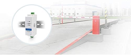
Figure 8: An example of the USR-DR302 being used in a barrier gate control system, likely for remote monitoring or control of the gate via Ethernet.

Figure 9: Depiction of multiple USR-DR302 devices connecting various signal lights to a central server via an Ethernet network, enabling centralized control and monitoring.
Warranty and Support
Information regarding product warranty, technical support, and service centers is typically provided by the manufacturer or your point of purchase. Please refer to the documentation included with your product or visit the official PUSR website for the most current and detailed information.
For further assistance, you may contact PUSR customer support through their official channels.


