
1. Introduction
This manual provides detailed instructions for the installation, operation, and maintenance of your GCSOAR Solar Charge Controller. This PWM solar regulator is designed for 12V/24V auto work systems, supporting a maximum PV input of 300W/600W. It features dual 5V USB ports, an LCD display, overload protection, and timer settings for efficient and safe solar energy management.

Figure 1.1: The GCSOAR Solar Charge Controller (Model GC2024) and its retail packaging.
2. Safety Information
Please read all instructions carefully before installation and operation. Failure to follow these instructions may result in damage to the unit, personal injury, or property damage. Keep this manual for future reference.
- Ensure all connections are correct and secure before applying power.
- Always connect the battery first, then the load, and finally the solar panel. Disconnect in the reverse order.
- The regulator is only suitable for lead-acid batteries (OPEN, AGM, GEL). It is not compatible with nickel-hydride, lithium-ion, or other battery types.
- Ensure your battery has sufficient voltage for the controller to recognize it before the first installation.
- The working temperature of this controller is -35°C to 60°C. During hot sunny days, the temperature outside might reach 60-75°C. Please keep the controller in a cool and well-ventilated place to maintain good heat dissipation.
- Do not use an electric screwdriver to tighten the screws on the terminals.
- This device is for indoor use only. Protect it from water and moisture.
3. Product Overview
The GCSOAR Solar Charge Controller is a Pulse Width Modulation (PWM) device designed to manage power flow from your solar panel to your battery and load. It features a clear LCD display for monitoring system status and easy parameter adjustment.
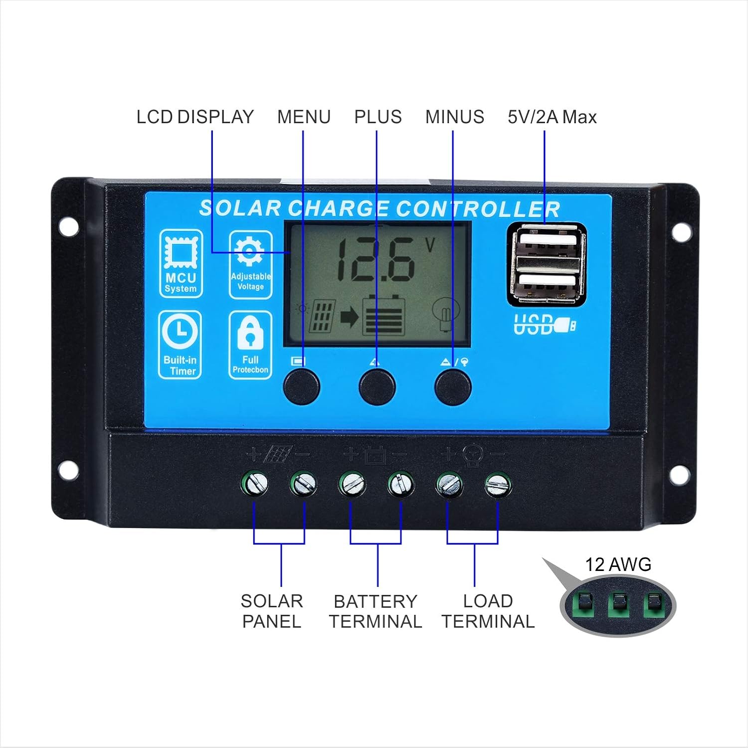
Figure 3.1: Front view of the GCSOAR Solar Charge Controller, highlighting the LCD display, control buttons, and dual USB ports.
Key Features:
- Dual MOSFET reverse current protection.
- Low heat production.
- Built-in short-circuit protection, open-circuit protection.
- Large LCD display with adjustable parameters.
- Fully 3-stage PWM charge management.
- Reverse protection, over-load protection.
- Built-in industrial micro controller.
- Dual USB 5V/2A output.

Figure 3.2: Internal view of the GCSOAR Solar Charge Controller, illustrating the robust circuit components for stable operation.
4. Setup and Installation
Proper installation is critical for the safe and efficient operation of your solar charge controller. Please follow these steps carefully.
Installation Steps:
- Prepare the Wires: Ensure all wires are properly stripped and ready for connection. Loosen the screw terminals on the controller.
Video 4.1: This video demonstrates the unboxing, component identification, and initial wiring steps for the PWM solar charge controller, including how to loosen the screw terminals for wire insertion.
- Connect the Battery: Connect the battery to the charge controller first. Ensure correct polarity (+ to + and - to -).
- Connect the Load: Connect the DC load to the charge controller. Again, observe correct polarity.
- Connect the Solar Panel: Finally, connect the solar panel (PV array) to the charge controller. Ensure correct polarity.

Figure 4.2: Wiring diagram illustrating the connection sequence: Battery first, then load, then solar panel. This diagram shows the solar panel, charge controller, battery, inverter, and various loads.
Important: Always connect the battery first and disconnect the solar panel first when disassembling the system.
5. Operating Instructions
The LCD display provides real-time information about your solar system. Use the buttons to navigate and adjust settings.
Button Functions:
- MENU Button: Press to browse different interfaces. Long press to enter setting mode (in interfaces 2-5).
- UP (+) Button: Used to increase values or navigate up in menus.
- DOWN/ON/OFF (-) Button: Used to decrease values or navigate down in menus. Also used to turn the load ON/OFF.

Figure 5.1: LCD display interface showing different screens for browsing system status and setting parameters.
Display Interfaces:
The controller cycles through various display screens. Press the MENU button to manually switch between them.
- Main Display (Battery Voltage, Solar Charging Status, Load Status)
- Float or CV Voltage
- Discharge Reconnect Voltage
- Discharge Stop Voltage
- Work Mode (Timer Setting)
- Battery Type (b01 Sealed, b02 GEL, b03 Flood)
Parameter Setting:
To set parameters (in interfaces 2-5):
- Long press the MENU button to enter setting mode. The displayed value will start flashing.
- Use the UP (+) and DOWN (-) buttons to adjust the parameter value.
- Long press the MENU button again to save the setting and exit.

Figure 5.2: Examples of different information screens on the LCD display, including battery voltage, charging status, and load settings.
6. Maintenance
Regular maintenance ensures the longevity and optimal performance of your solar charge controller.
- Keep the controller clean and free from dust.
- Ensure proper ventilation around the unit to prevent overheating.
- Periodically check all wire connections for tightness and corrosion.
- Inspect the controller for any signs of physical damage.
7. Troubleshooting
If you encounter issues with your GCSOAR Solar Charge Controller, refer to the following common problems and solutions:
| Problem | Possible Cause | Solution |
|---|---|---|
| Controller not turning on / No display | Battery not connected or low voltage; reversed polarity. | Check battery connections and voltage. Ensure battery voltage is above 8V. Correct polarity if reversed. |
| Battery not charging | Solar panel not connected; low solar input; faulty solar panel or wiring. | Check solar panel connections and ensure sufficient sunlight. Test solar panel voltage. |
| Load not working | Load output off; overload protection activated; faulty load wiring. | Press the DOWN (-) button to turn on the load. Reduce load if overloaded. Check load connections. |
| Inaccurate voltage readings | Loose connections; incorrect battery type setting. | Tighten all terminal connections. Verify the correct battery type is selected in the settings. |
8. Specifications
| Feature | Detail |
|---|---|
| Brand | GCSOAR |
| Model | GC2024 |
| System Voltage | 12V / 24V Auto Work |
| Rated Charge Current | 20A |
| Rated Discharge Current | 20A |
| Max PV Input Power (12V) | 300W |
| Max PV Input Power (24V) | 600W |
| Max Solar Input Voltage | <50V |
| Display Type | LCD |
| USB Output | Dual 5V/2A Max |
| Product Dimensions | 5.24 x 2.76 x 1.3 inches |
| Item Weight | 12 ounces |
| UPC | 791324130176 |
9. Support
For technical assistance or any inquiries regarding your GCSOAR Solar Charge Controller, please contact our support team. GCSOAR has established warehouses and assistance centers in Chicago (USA), Munich (Germany), Toronto (Canada), and Melbourne (Australia) to provide free technical assistance to our customers.
For more information, visit the GCSOAR Store on Amazon.