1. Product Overview
The FlowServe 218822.999.000 LOGIX 500SI Valve Positioner Potentiometer is a critical component designed for precise feedback in valve positioning systems. This potentiometer provides accurate electrical resistance feedback corresponding to the valve's physical position, ensuring reliable operation and control within industrial applications.
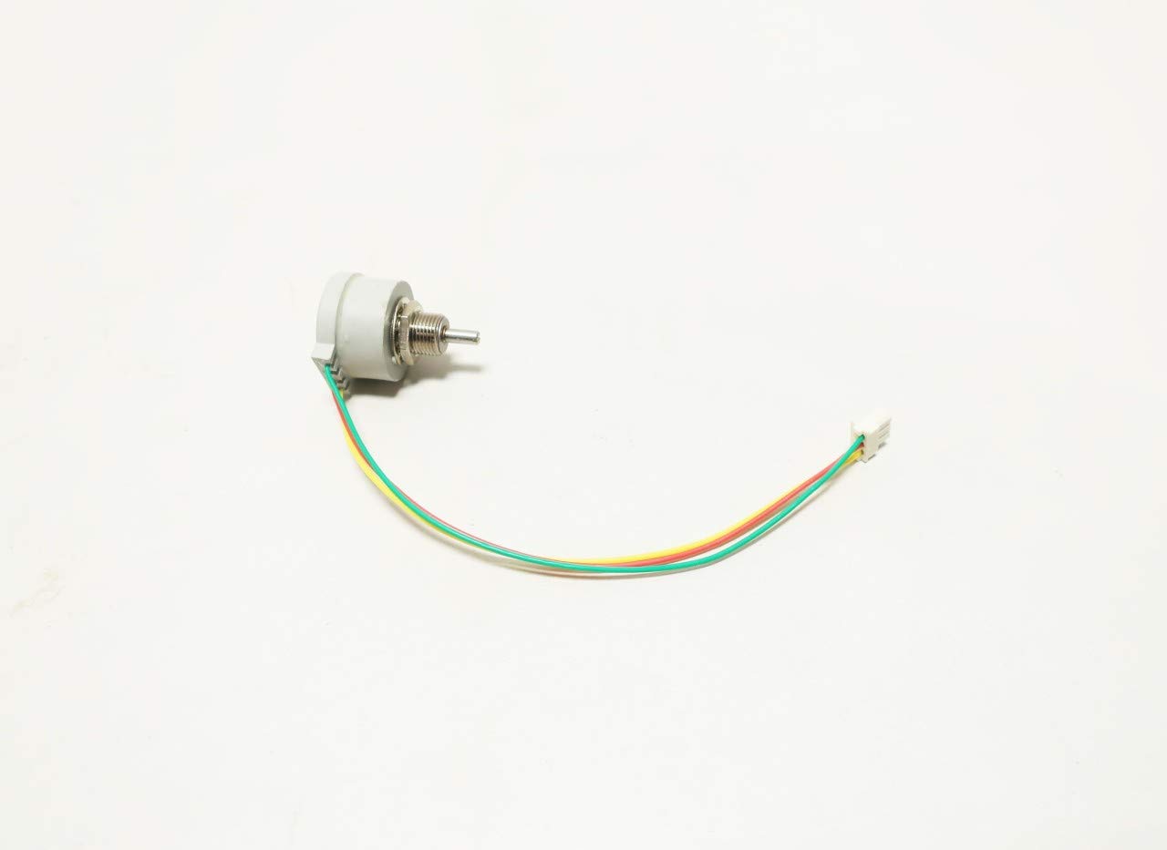
Figure 1.1: Overall view of the FlowServe LOGIX 500SI Valve Positioner Potentiometer, showing the main body, shaft, and connected wiring harness with a white connector.
2. Key Features and Components
- Precision Feedback: Designed for accurate position sensing in valve applications.
- Durable Construction: Built to withstand industrial environments.
- Integrated Wiring: Comes with a pre-attached wiring harness for ease of installation.
- Model Identification: Part number 218822.999.000, associated with LOGIX 500SI valve positioners.

Figure 2.1: Close-up view of the potentiometer's threaded shaft and slotted end, designed for mechanical coupling.

Figure 2.2: Detailed view of the white multi-pin connector at the end of the wiring harness, showing the individual wire terminals.

Figure 2.3: View of the potentiometer's body displaying manufacturing details including "BT 6186-200D R50K L5 0843 MEXICO" and rotation indicators "CW" (Clockwise) and "CCW S" (Counter-Clockwise Start).
3. Setup and Installation
Proper installation is crucial for the accurate and reliable operation of the potentiometer. Refer to the specific valve positioner's manual for detailed mounting instructions.
- Mounting: Securely attach the potentiometer to the designated mounting point on the LOGIX 500SI valve positioner. Ensure the shaft is correctly aligned with the valve's feedback mechanism.
- Mechanical Connection: Connect the potentiometer shaft to the valve's moving part, ensuring smooth rotation throughout the valve's full range of motion. Avoid overtightening or applying excessive force.
- Electrical Connection: Connect the wiring harness to the corresponding terminals on the valve positioner's control board. Pay close attention to wire color coding (typically red, yellow, green) to ensure correct polarity and signal integrity.
- Verification: After installation, manually actuate the valve through its full range of motion and verify that the potentiometer rotates freely without binding.

Figure 3.1: Original product packaging showing a barcode and the internal part number 1518283, which may be relevant for inventory or specific system integration. This packaging also indicates "FLOWSERV REMOTE FOR LOW NOX DAMPERS".
For more information on this specific part, refer to FlowServe's official documentation for LOGIX 500SI.
4. Operating Principles
The potentiometer functions as a variable resistor, providing an electrical signal proportional to its angular position. As the valve moves, the potentiometer's shaft rotates, changing its resistance. This change in resistance is then converted into a voltage signal by the valve positioner's electronics, indicating the exact position of the valve.
- Feedback Loop: The signal from the potentiometer is fed back to the control system, allowing it to precisely adjust the valve's position to the desired setpoint.
- Calibration: After installation, the valve positioner typically requires calibration to map the potentiometer's electrical output to the physical travel limits of the valve. Refer to the valve positioner's manual for calibration procedures.
5. Maintenance
The FlowServe potentiometer is designed for long-term reliability with minimal maintenance. However, periodic checks are recommended to ensure optimal performance.
- Visual Inspection: Periodically inspect the potentiometer and its wiring for any signs of physical damage, corrosion, or loose connections.
- Shaft Movement: Ensure the potentiometer shaft rotates smoothly without any stiffness or excessive play.
- Cleaning: If operating in a dusty environment, gently clean the exterior of the potentiometer with a soft, dry cloth. Avoid using solvents or abrasive cleaners.
- Electrical Testing: If performance issues arise, test the resistance output of the potentiometer across its range of motion using a multimeter to verify its functionality.
6. Troubleshooting
This section provides guidance for common issues. For complex problems, consult a qualified technician or FlowServe support.
| Problem | Possible Cause | Solution |
|---|---|---|
| Inaccurate Valve Position Feedback |
|
|
| No Signal Output |
|
|
| Stiff or Binding Shaft |
|
|

Figure 6.1: Another view of the product packaging, clearly showing the FlowServe part number 218822.999.000 for the LOGIX 500SI Valve Positioner Potentiometer, along with an internal tracking number 735640. This label confirms the product's identity and application.
7. Specifications
| Attribute | Value |
|---|---|
| Model Number | 218822.999.000 |
| Associated Series | LOGIX 500SI Valve Positioner |
| Manufacturer | FLOWSERVE |
| Product Type | Potentiometer (Valve Positioner Feedback) |
| Product Dimensions | 7 x 3.5 x 1 inches |
| Product Weight | 1.2 Pounds |
| First Available Date | December 20, 2019 |
8. Warranty and Support
Specific warranty information for the FlowServe 218822.999.000 LOGIX 500SI Valve Positioner Potentiometer should be obtained directly from FlowServe or your authorized distributor at the time of purchase. Generally, industrial components carry a manufacturer's warranty against defects in materials and workmanship.
For technical support, spare parts, or service inquiries, please contact FlowServe customer service or your local FlowServe representative. Always provide the full model number (218822.999.000) and any relevant serial numbers when seeking support.
FlowServe Official Website: www.flowserve.com