
uxcell a19091100ux0717
Contents
uxcell Red Indicator Light with Buzzer User Manual
Model: a19091100ux0717
Product Overview
The uxcell Red Indicator Light with Buzzer is designed for various electrical control applications. It features a high-brightness red LED and an intermittent buzzer, operating on AC/DC 24V. This unit is suitable for panel mounting with an industrial standard 28mm diameter.
It is commonly used in ship controls, machine tools, general machine equipment, switch cabinets, power distribution cabinets, HVAC panels, and for DIY projects like PLC training.
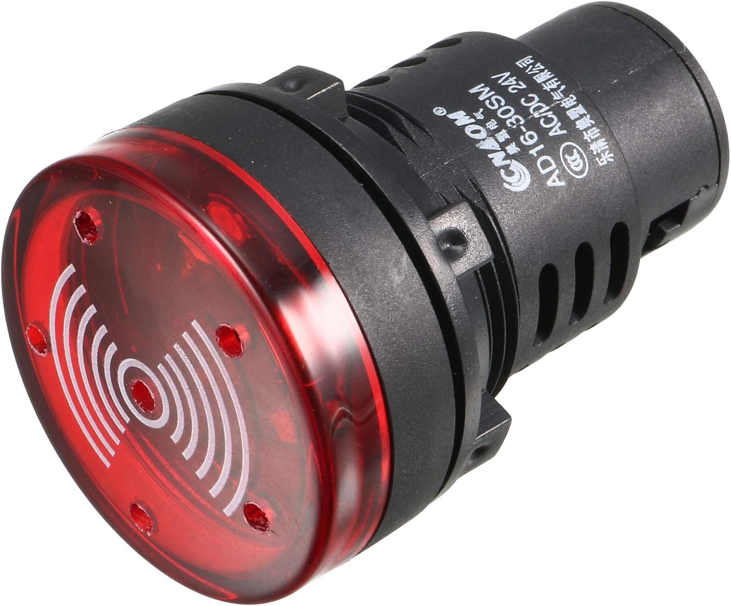
Figure 1: Front view of the uxcell Red Indicator Light with Buzzer.
Specifications
| Feature | Detail |
|---|---|
| Model Number | a19091100ux0717 |
| Color | Red |
| Voltage | AC/DC 24V |
| Mounting Diameter | 28mm (1-1/10") |
| Head Diameter | 36mm (1.42") |
| Overall Length | 53mm (2.09") |
| Fits Panel Thickness | ≤6mm (0.24") |
| Light Source Type | LED |
| Features | Flashing Light, Intermittent Buzzer |
| Working Life | >30,000 hours |
| Material | Copper |
| Item Weight | 0.81 ounces |

Figure 2: Detailed dimensions of the indicator light, showing head diameter, mounting hole diameter, and overall length.

Figure 3: Technical drawing illustrating all key dimensions and panel thickness compatibility.
Safety Information
Warning: Always disconnect power before installation or maintenance to prevent electric shock.
Ensure proper voltage (AC/DC 24V) is supplied to the unit. Incorrect voltage may damage the device or pose a safety hazard.
Do not overtighten the screw terminals during wiring, as this may cause damage to the unit.
This product contains chemicals known to the State of California to cause cancer and birth defects or other reproductive harm (Proposition 65 warning). Handle with care and wash hands after handling.
Setup and Installation
- Prepare Panel: Drill a 28mm (1-1/10") diameter mounting hole in your control panel. Ensure the panel thickness does not exceed 6mm (0.24").
- Insert Indicator: Insert the indicator light into the prepared hole from the front of the panel.
- Secure with Nut: From the back of the panel, thread and tighten the included panel locking nut onto the indicator light to secure it firmly in place.
- Wire Connections: Connect the AC/DC 24V power supply wires to the screw-clamp terminals at the rear of the indicator light. Ensure connections are firm but do not overtighten the screws.
- Dust Cap (Optional): If desired, install the dust cap over the rear terminals to protect against dust and environmental hazards.

Figure 4: Rear view of the indicator light, showing the screw-clamp terminals for wiring connections.

Figure 5: The removable dust cap designed to protect the rear terminals from dust.
Operating Instructions
Once properly installed and wired, the uxcell Red Indicator Light with Buzzer will activate when the specified AC/DC 24V power is applied to its terminals.
- Light Indication: The red LED will illuminate and flash when power is supplied, indicating the operational status of the connected circuit or equipment.
- Buzzer Alarm: Concurrently with the flashing light, the intermittent buzzer will sound, providing an audible alert.
- Deactivation: The light and buzzer will turn off when the power supply to the unit is disconnected.

Figure 6: The indicator light showing its illuminated state, signifying active operation.
Maintenance
The uxcell Red Indicator Light with Buzzer is designed for long-term, maintenance-free operation with a working life of over 30,000 hours.
- Cleaning: Periodically wipe the surface of the indicator light with a soft, dry cloth to remove dust and debris. Do not use abrasive cleaners or solvents.
- Connection Check: Occasionally inspect the wiring connections at the rear of the unit to ensure they remain secure. Re-tighten if necessary, but avoid overtightening.
- Dust Cap: Ensure the dust cap (if installed) is properly seated to protect the terminals from environmental elements.
Troubleshooting
| Problem | Possible Cause | Solution |
|---|---|---|
| Light and/or Buzzer not activating. | No power supply. Incorrect voltage. Loose wiring connections. Damaged unit. | Verify power supply (AC/DC 24V) is active. Check input voltage matches specifications. Inspect and secure all wiring connections. If all else fails, the unit may be faulty and require replacement. |
| Buzzer not sounding, but light is flashing. | Buzzer component failure. | The buzzer component may be damaged. Consider replacing the unit if the audible alarm is critical. |
| Light is dim or flickering. | Insufficient voltage. Poor connection. | Verify stable 24V power supply. Check wiring for loose or corroded connections. |
Warranty and Support
For warranty information or technical support, please contact uxcell directly through their official channels or the retailer from whom the product was purchased.
Visit the official uxcell store for more products and support: uxcell Store on Amazon
Ask a question about this manual
Ask about setup, troubleshooting, compatibility, parts, safety, or missing instructions. Manuals+ will review the question and use this page’s manual context to help answer it.