1. Introduction
The ANENG AN8301 is a portable digital multimeter designed for accurate measurement of various electrical parameters. It is suitable for professional, educational, and hobbyist use in testing DC/AC voltage, DC/AC current, resistance, capacitance, diode, and transistor hFE. This manual provides essential information for safe and effective operation of your device.
2. Safety Information
WARNING: To avoid possible electric shock or personal injury, and to avoid possible damage to the meter or to the equipment under test, adhere to the following safety rules:
- Always ensure the function switch is set to the correct range before making any measurements.
- Do not apply more than the rated voltage, as marked on the meter, between the terminals or between any terminal and earth ground.
- Inspect test leads for damaged insulation or exposed metal. Replace if damaged.
- Do not use the meter if it appears damaged or if the case is open.
- Exercise extreme caution when working with voltages above 60V DC or 30V AC RMS. Such voltages pose a shock hazard.
- Remove test leads from the circuit before changing the function or range.
- Replace the battery as soon as the low battery indicator appears to ensure accurate readings.
- Always disconnect power to the circuit and discharge all high-voltage capacitors before testing resistance, continuity, diodes, or capacitance.
3. Product Overview
The ANENG AN8301 Digital Multimeter features a clear LCD display, a rotary function switch, and multiple input jacks for various measurements.
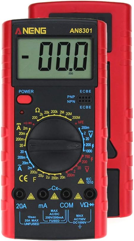
Figure 3.1: Front view of the ANENG AN8301 Digital Multimeter, showing the LCD display, rotary switch, and input terminals.
Key Components:
- LCD Display: Shows measurement readings, units, and other indicators.
- Power Button: Turns the multimeter on or off.
- Rotary Function Switch: Selects the desired measurement function and range.
- Input Jacks: Terminals for connecting test leads (VΩHz, COM, mA, 20A).
- hFE Socket: For testing transistors (PNP/NPN).
4. Setup
4.1 Battery Installation
The ANENG AN8301 requires a 9V (6F22) battery for operation. Follow these steps to install or replace the battery:
- Ensure the multimeter is powered off and test leads are disconnected.
- Locate the battery compartment cover on the back of the unit.
- Unscrew the retaining screw(s) and carefully remove the cover.
- Connect a new 9V battery to the battery clip, observing correct polarity.
- Place the battery into the compartment and replace the cover, securing it with the screw(s).

Figure 4.1: Rear view of the ANENG AN8301 showing the open battery compartment for 9V battery installation.
4.2 Connecting Test Leads
To prepare for measurements, connect the test leads as follows:
- Insert the black test lead into the COM (common) jack.
- For most voltage, resistance, and capacitance measurements, insert the red test lead into the VΩHz jack.
- For current measurements up to 200mA, insert the red test lead into the mA jack.
- For high current measurements (up to 20A), insert the red test lead into the 20A jack.
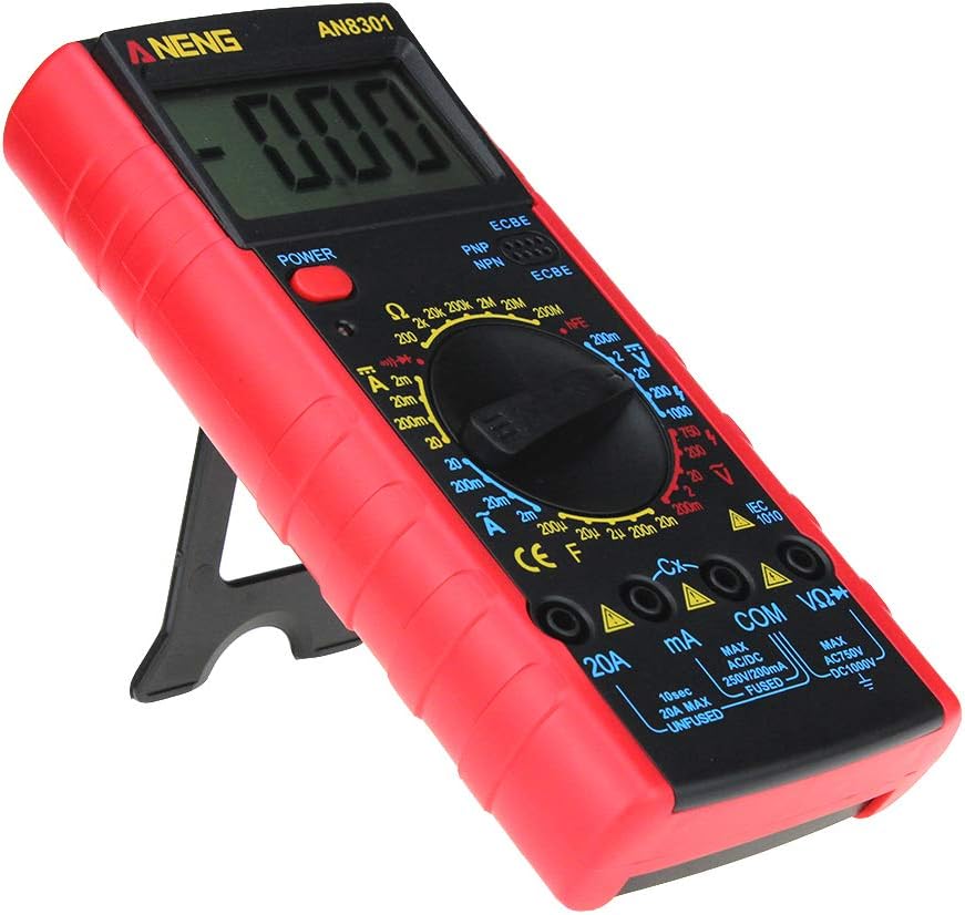
Figure 4.2: The ANENG AN8301 Multimeter shown with its included test leads and instruction manual.
5. Operating Instructions
5.1 General Operation
- Press the POWER button to turn on the multimeter.
- Select the desired measurement function by rotating the function switch.
- Connect the test leads to the circuit or component under test.
- Read the measurement value on the LCD display.
- After use, press the POWER button to turn off the multimeter.
5.2 Specific Measurements
Always ensure the correct function and range are selected before connecting the test leads to the circuit.
- DC Voltage (V—):
1. Set the rotary switch to the desired DCV range (e.g., 20V, 200V).
2. Connect the red test lead to the positive side and the black test lead to the negative side of the DC voltage source in parallel. - AC Voltage (V∼):
1. Set the rotary switch to the desired ACV range (e.g., 200V, 750V).
2. Connect the test leads across the AC voltage source in parallel. - DC Current (A—):
1. Set the rotary switch to the desired DCA range (e.g., 20mA, 200mA, 20A).
2. Connect the multimeter in series with the circuit. Ensure the red lead is in the appropriate current jack (mA or 20A). - AC Current (A∼):
1. Set the rotary switch to the desired ACA range (e.g., 20mA, 200mA, 20A).
2. Connect the multimeter in series with the circuit. Ensure the red lead is in the appropriate current jack (mA or 20A). - Resistance (Ω):
1. Set the rotary switch to the desired Ω range.
2. Ensure the circuit is de-energized. Connect the test leads across the component to measure its resistance. - Capacitance (F):
1. Set the rotary switch to the desired capacitance range (e.g., 20nF, 200nF, 2µF).
2. Ensure the capacitor is fully discharged before connecting the test leads. - Diode Test (→|):
1. Set the rotary switch to the diode symbol.
2. Connect the red lead to the anode and the black lead to the cathode of the diode. The forward voltage drop will be displayed. Reverse the leads to check for open circuit. - Transistor (hFE) Test:
1. Set the rotary switch to the hFE position.
2. Insert the transistor leads (Emitter, Base, Collector) into the corresponding holes in the hFE socket, ensuring correct PNP or NPN type. - Continuity Test (♫):
1. Set the rotary switch to the continuity symbol.
2. Connect the test leads across the circuit or component. A continuous beep indicates a complete circuit (low resistance).

Figure 5.1: The ANENG AN8301 Multimeter displaying a voltage reading while connected to a 9V battery using test clips.
6. Maintenance
6.1 Battery Replacement
When the low battery indicator appears on the display, replace the 9V battery immediately to ensure accurate measurements. Refer to Section 4.1 for detailed instructions.
6.2 Fuse Replacement
If the current measurement function fails, the fuse may need replacement. The ANENG AN8301 typically uses two fuses: a 250V/200mA fast-acting fuse for the mA range and a 20A unfused input for the 20A range (check markings on the device). To replace a fuse:
- Ensure the multimeter is powered off and all test leads are disconnected.
- Open the back case of the multimeter (this may require removing multiple screws).
- Carefully locate and remove the blown fuse.
- Replace it with a fuse of the exact same type and rating.
- Reassemble the case securely.
6.3 Cleaning and Storage
Wipe the case with a damp cloth and mild detergent. Do not use abrasives or solvents. For long-term storage, remove the battery to prevent leakage and store the multimeter in a cool, dry place.
7. Troubleshooting
- No display or dim display:
- Check battery charge. Replace the 9V battery if low.
- Ensure the power button is pressed. - Incorrect or unstable readings:
- Ensure test leads are properly connected to the correct input jacks.
- Verify the function switch is set to the appropriate range.
- Check for loose connections or damaged test leads.
- Ensure the battery is not low. - "OL" (Overload) displayed:
- The measured value exceeds the selected range. Switch to a higher range.
- The input value exceeds the maximum input limit of the meter. Disconnect immediately. - Current measurement not working:
- Check if the fuse for the current range is blown. Replace if necessary (refer to Section 6.2).
- Ensure the red test lead is in the correct current input jack (mA or 20A).
8. Specifications
| Parameter | Specification |
|---|---|
| DC Voltage | 200mV, 2V, 20V, 200V, 1000V (±0.5%) |
| AC Voltage | 200mV, 2V, 20V, 200V, 750V (±1.0%) |
| DC Current | 2mA, 20mA, 200mA, 20A (±1.0%) |
| AC Current | 2mA, 20mA, 200mA, 20A (±1.5%) |
| Resistance | 200Ω, 2kΩ, 20kΩ, 200kΩ, 2MΩ, 20MΩ, 200MΩ (±1.0%) |
| Capacitance | 20nF, 200nF, 2µF, 20µF, 200µF (±4.0%) |
| Diode Test | Yes |
| Transistor (hFE) Test | Yes |
| Display | 3½ digit LCD, maximum display value 1999 |
| Power Supply | 9V battery (6F22) |
| Dimensions | 182mm x 90mm x 30mm |
| Weight | Approximately 250g |
| UPC | 630282714328 |
9. Warranty and Support
For warranty information or technical support, please refer to the documentation provided with your purchase or contact the seller/manufacturer directly. Keep your purchase receipt as proof of purchase.


