1. Introduction
This manual provides detailed instructions for the safe and effective use of your ANENG AN8004 Digital Multimeter. Please read this manual thoroughly before operation and retain it for future reference.
The ANENG AN8004 is a compact, auto-ranging digital multimeter designed for measuring AC/DC voltage, AC/DC current, resistance, capacitance, frequency, duty cycle, diode, and continuity. It features a large LCD display with backlight, data hold, relative measurement, and auto power-off functions.
2. Safety Information
WARNING: To avoid electric shock or personal injury, and to avoid damage to the meter or to the equipment under test, observe the following safety rules:
- Always ensure the meter is in the correct function and range before making measurements.
- Do not apply more than the rated voltage, as marked on the meter, between the terminals or between any terminal and earth ground.
- Use extreme caution when working with voltages above 30V AC RMS, 42V peak, or 60V DC. These voltages pose a shock hazard.
- Disconnect the test leads from the circuit before changing functions.
- Never connect the test leads to a voltage source when the rotary switch is set to current, resistance, or diode/continuity mode.
- Replace the battery as soon as the low battery indicator appears to avoid incorrect readings.
- Do not operate the meter if it appears damaged or if the case is not fully closed.
- Ensure the test leads are in good condition, with no damaged insulation.
3. Product Components and Overview
The ANENG AN8004 Digital Multimeter comes with the main unit and essential accessories for various measurements.

Figure 3.1: ANENG AN8004 Digital Multimeter with included test leads and alligator clips. This image shows the complete package, including the main multimeter unit, standard test probes (red and black), and a pair of alligator clip adapters.

Figure 3.2: Front view of the ANENG AN8004 Digital Multimeter. This image highlights the large LCD display, the central rotary switch for function selection, and the input jacks for test leads.
3.1. Key Features
- Auto-ranging for simplified operation.
- 550V protection in Resistance, Capacitance, and Frequency ranges.
- Large LCD display with a maximum count of 1999.
- Sample rate: 3 times per second.
- Backlight for visibility in low-light conditions.
- Data Hold function to freeze readings.
- Relative Measurement mode.
- Polarity identification.
- Low voltage indication for battery replacement.
- 10A high current and low current measurement capabilities.
- Auto Power Off to conserve battery life.
4. Setup and Preparation
4.1. Battery Installation
The ANENG AN8004 Multimeter requires two (2) AAA 1.5V batteries (not included) for operation.
- Ensure the multimeter is turned OFF.
- Locate the battery compartment cover on the back of the unit.
- Use a screwdriver to remove the screw securing the battery cover.
- Carefully remove the cover.
- Insert two AAA batteries, observing the correct polarity (+ and -) as indicated inside the compartment.
- Replace the battery cover and secure it with the screw.
4.2. Connecting Test Leads
Always connect the test leads correctly for accurate and safe measurements.

Figure 4.1: ANENG AN8004 Multimeter with test leads properly connected. The black lead is inserted into the 'COM' jack, and the red lead is inserted into the 'VΩHz' jack for voltage, resistance, and frequency measurements.
- Insert the black test lead into the COM (Common) input jack.
- For most voltage, resistance, frequency, capacitance, and diode/continuity measurements, insert the red test lead into the VΩHz input jack.
- For current measurements (mA/µA), insert the red test lead into the mAµA input jack.
- For high current measurements (10A), insert the red test lead into the 10A input jack.
5. Operating Instructions
Turn the rotary switch to the desired function. The meter is auto-ranging, simplifying operation.
5.1. DC Voltage Measurement
- Insert the black lead into the COM jack and the red lead into the VΩHz jack.
- Turn the rotary switch to the V (DC Voltage) position.
- Connect the test probes across the component or circuit to be measured.
- The display will show the DC voltage reading.

Figure 5.1: Example of measuring DC voltage using the ANENG AN8004 Multimeter. The image shows the multimeter connected to a 9V battery using alligator clip test leads, displaying a voltage reading.
5.2. AC Voltage Measurement
- Insert the black lead into the COM jack and the red lead into the VΩHz jack.
- Turn the rotary switch to the V~ (AC Voltage) position.
- Connect the test probes across the AC voltage source.
- The display will show the AC voltage reading.
5.3. DC Current Measurement
- IMPORTANT: Disconnect power to the circuit before connecting the meter in series.
- Insert the black lead into the COM jack.
- For currents up to 400mA, insert the red lead into the mAµA jack.
- For currents up to 10A, insert the red lead into the 10A jack.
- Turn the rotary switch to the mA or µA (DC Current) position, or the 10A position.
- Connect the meter in series with the circuit.
- Apply power to the circuit. The display will show the DC current reading.
5.4. AC Current Measurement
- IMPORTANT: Disconnect power to the circuit before connecting the meter in series.
- Insert the black lead into the COM jack.
- For currents up to 400mA, insert the red lead into the mAµA jack.
- For currents up to 10A, insert the red lead into the 10A jack.
- Turn the rotary switch to the mA~ or µA~ (AC Current) position, or the 10A~ position.
- Connect the meter in series with the circuit.
- Apply power to the circuit. The display will show the AC current reading.
5.5. Resistance Measurement
- Insert the black lead into the COM jack and the red lead into the VΩHz jack.
- Turn the rotary switch to the Ω (Resistance) position.
- Ensure the circuit or component is de-energized before measuring resistance.
- Connect the test probes across the resistor or component.
- The display will show the resistance reading. If "OL" indicates out of range or open circuit.
5.6. Diode and Continuity Test
- Insert the black lead into the COM jack and the red lead into the VΩHz jack.
- Turn the rotary switch to the Diode/Continuity position (often indicated by a diode symbol and a sound wave symbol).
- For Diode Test: Connect the red probe to the anode and the black probe to the cathode of the diode. The display will show the forward voltage drop. Reverse the probes; the display should show "OL" for a good diode.
- For Continuity Test: Connect the probes across the circuit or component. If resistance is below approximately 50Ω, the buzzer will sound, indicating continuity.
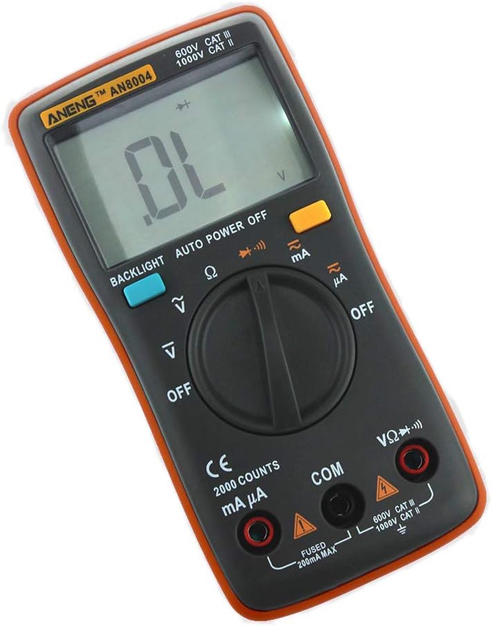
Figure 5.2: The multimeter display showing "OL", indicating an Overload or Out of Range condition. This can occur during resistance or diode tests if the circuit is open or the value exceeds the meter's maximum range.
5.7. Capacitance Measurement
- Insert the black lead into the COM jack and the red lead into the VΩHz jack.
- Turn the rotary switch to the Capacitance position (often indicated by a capacitor symbol).
- WARNING: Discharge capacitors before testing to prevent electric shock or damage to the meter.
- Connect the test probes across the capacitor.
- The display will show the capacitance value.
5.8. Frequency and Duty Cycle Measurement
- Insert the black lead into the COM jack and the red lead into the VΩHz jack.
- Turn the rotary switch to the Hz/% (Frequency/Duty Cycle) position.
- Connect the test probes across the signal source.
- The display will show the frequency in Hz. Press the "SELECT" button (if available) to switch to duty cycle measurement.
5.9. Function Buttons
- BACKLIGHT: Press to turn on/off the display backlight.
- AUTO POWER OFF: The meter automatically turns off after a period of inactivity to save battery.
- DATA HOLD: Press to freeze the current reading on the display. Press again to release.
- RELATIVE MEASUREMENT: Press to store the current reading as a reference and display subsequent readings as a difference from this reference.
6. Maintenance
6.1. Cleaning
Wipe the case with a damp cloth and mild detergent. Do not use abrasives or solvents. Keep the input terminals free of dirt and moisture.
6.2. Battery Replacement
When the low battery indicator appears on the display, replace the batteries immediately to ensure accurate readings. Refer to Section 4.1 for battery installation instructions.
6.3. Fuse Replacement
The meter is protected by internal fuses. If the current measurement function fails, the fuse may need replacement. This procedure should only be performed by qualified personnel. Use only fuses of the specified type and rating.
7. Troubleshooting
| Problem | Possible Cause | Solution |
|---|---|---|
| Meter does not power on. | Dead or incorrectly installed batteries. | Check battery polarity; replace batteries. |
| "OL" (Overload) displayed. | Measurement exceeds selected range; open circuit (resistance/continuity). | Select a higher range (if manual ranging); check for open circuit; ensure probes are making good contact. |
| Inaccurate readings. | Low battery; incorrect function/range; poor probe contact; external interference. | Replace batteries; verify function/range; clean probes; move away from strong electromagnetic fields. |
| No current reading. | Blown fuse; incorrect input jack; meter not in series. | Check/replace fuse; ensure red lead is in mAµA or 10A jack; connect meter in series with the load. |
8. Technical Specifications

Figure 8.1: Physical dimensions of the ANENG AN8004 Digital Multimeter. The image indicates a length of approximately 130.5mm (5.13in) and a width of 65.4mm (2.57in).
| Measurement | Range | Accuracy |
|---|---|---|
| DC Voltage | 400mV / 4V / 40V / 400V / 600V | ±(0.5%+4) for 400mV-40V, ±(0.8%+4) for 400V-600V |
| AC Voltage | 400mV / 4V / 40V / 400V / 600V | ±(1.5%+4) for 400mV, ±(1.2%+4) for 4V-400V, ±(1.5%+4) for 600V |
| DC Current | 40mA / 400mA / 10A | ±(1.0%+4) for 40mA-400mA, ±(1.5%+4) for 10A |
| AC Current | 40mA / 400mA / 10A (50-200Hz) | ±(2.0%+4) |
| Resistance | 400Ω / 4KΩ / 40KΩ / 400KΩ / 4MΩ / 40MΩ | ±(0.8%+4) for 400Ω-4MΩ, ±(2.0%+4) for 40MΩ |
| Frequency | 99.5Hz / 999.5Hz / 9.999kHz / 99.99kHz / 999.9kHz / 9.999MHz | ±(0.08%+2) |
| Duty Cycle | 0.1% to 99.9% | ±(0.08%+2) |
| Power Supply | 2 x 1.5V AAA Batteries | |
| Dimensions | 130 x 65 x 30 mm | |
| Weight | Approx. 200g | |
| Working Environment | 0~40°C, relative humidity <80% |
General Specifications:
- Brand: ANENG
- Model: AN8004
- Measurement Type: Multimeter
- Style: Digital
- UPC: 630282713826
- Manufacturer: China
- First Available: November 27, 2019
9. Warranty Information
Specific warranty details are not provided in the product information. Please refer to the retailer or manufacturer's official website for warranty terms and conditions. Typically, electronic devices come with a limited manufacturer's warranty covering defects in materials and workmanship for a specified period from the date of purchase.
10. Customer Support
For technical assistance, troubleshooting beyond this manual, or inquiries regarding your ANENG AN8004 Digital Multimeter, please contact your point of purchase or refer to the official ANENG support channels. Keep your purchase receipt and product model number handy when contacting support.


