1. Introduction
The ANENG M1 is a compact, handheld digital multimeter designed for measuring various electrical parameters. It features a 3 1/2 digit LCD display and is capable of measuring DC and AC voltage, DC and AC current, resistance, diode, transistor (hFE), and continuity. This device is battery-operated and includes overload protection for safe operation.
Key features include:
- High precision measurements.
- Data hold function to freeze readings.
- Backlit LCD for visibility in low-light conditions.
- Overload protection across various ranges.
2. Safety Information
Always adhere to basic safety precautions when using this multimeter to prevent personal injury or damage to the meter or equipment under test.
- Maximum Input Voltage: Do not apply more than 600V DC or 600V AC RMS between the input terminals and earth ground.
- Current Measurement: Ensure the circuit is de-energized before connecting the meter in series for current measurements. The 10A range is unfused; exercise extreme caution.
- Overload Protection: The meter features overload protection up to 250V DC or AC RMS for current, resistance, and capacitance ranges, and 600V DC or AC RMS for voltage ranges.
- Battery and Fuse: Replace the battery when the low battery indicator appears. Use only the specified fuse (F 250mA/250V self-restoring fuse) for replacement.
- Inspection: Before each use, inspect the test leads for damage. Do not use the meter if it or the test leads appear damaged.
- Operating Environment: Use the meter within the specified operating environment (0 to 40°C, relative humidity < 80%).
3. Product Overview
The ANENG M1 multimeter features a clear LCD display, a rotary function switch, and multiple input jacks for various measurements.
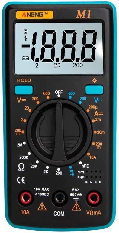
Figure 3.1: Front view of the ANENG M1 Digital Multimeter, showing the LCD display, rotary switch, and input terminals.
3.1 Components
- LCD Display: Shows measurement readings, units, and indicators (e.g., low battery, polarity).
- Rotary Function Switch: Used to select the desired measurement function and range.
- 'HOLD' Button: Freezes the current display reading. Press again to release.
- Backlight Button: Activates or deactivates the display backlight.
- 'VΩmA' Input Jack: Positive input for voltage, resistance, and low current measurements.
- 'COM' Input Jack: Common (negative) input for all measurements.
- '10A' Input Jack: Positive input for high current (up to 10A) measurements.
- hFE Socket: Used for transistor testing.

Figure 3.2: Close-up of the ANENG M1's HD digital display, illustrating its clear readability and compact design.

Figure 3.3: The ANENG M1 multimeter shown with its integrated back support, allowing it to stand on a flat surface for hands-free operation.
4. Setup
4.1 Battery Installation
The ANENG M1 multimeter requires a 9V battery (NEDA 1604 or 6F22) for operation.
- Ensure the multimeter is turned OFF.
- Locate the battery compartment on the back of the meter.
- Remove the screw(s) securing the battery cover and carefully open it.
- Connect a new 9V battery to the battery clip, observing correct polarity.
- Place the battery inside the compartment and replace the cover, securing it with the screw(s).
4.2 Connecting Test Leads
Always connect the test leads correctly for accurate and safe measurements.
- Insert the black test lead into the 'COM' (common) input jack.
- For most measurements (voltage, resistance, diode, transistor, low current), insert the red test lead into the 'VΩmA' input jack.
- For high current measurements (up to 10A), insert the red test lead into the '10A' input jack.
5. Operating Instructions
To begin, turn the rotary switch from 'OFF' to the desired measurement function.
5.1 DC Voltage Measurement (V=)
- Set the rotary switch to the desired 'V=' range (e.g., 200mV, 2V, 20V, 200V, 600V). If the voltage is unknown, start with the highest range and decrease as needed.
- Connect the red test lead to the positive (+) side of the circuit and the black test lead to the negative (-) side.
- Read the voltage value on the LCD display.
5.2 AC Voltage Measurement (V~)
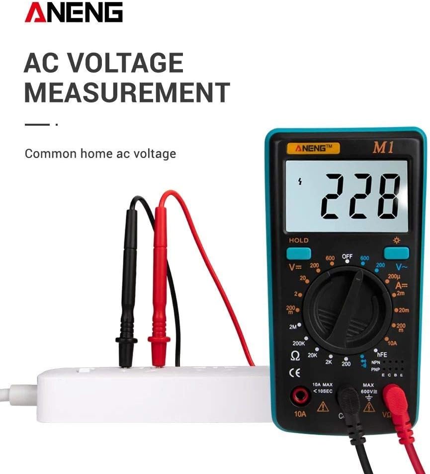
Figure 5.1: The ANENG M1 multimeter measuring AC voltage from a standard wall outlet, demonstrating proper test lead connection.
- Set the rotary switch to the desired 'V~' range (e.g., 200V, 600V).
- Connect the test leads across the AC voltage source.
- Read the voltage value on the LCD display.
5.3 DC Current Measurement (A=)
- Set the rotary switch to the desired 'A=' range (e.g., 200µA, 2mA, 20mA, 200mA, 10A).
- Important: Disconnect power to the circuit. Open the circuit where current is to be measured.
- Connect the meter in series with the circuit. For currents up to 200mA, use the 'VΩmA' jack. For currents up to 10A, use the '10A' jack.
- Apply power to the circuit and read the current value.
5.4 Resistance Measurement (Ω)
- Set the rotary switch to the desired 'Ω' range (e.g., 200Ω, 2KΩ, 20KΩ, 200KΩ, 2MΩ).
- Ensure the circuit or component under test is de-energized.
- Connect the test leads across the component.
- Read the resistance value on the LCD display.
5.5 Diode Test
- Set the rotary switch to the diode symbol (►|).
- Connect the red test lead to the anode and the black test lead to the cathode of the diode. A forward voltage drop will be displayed.
- Reverse the leads. An open circuit ('1') should be displayed for a good diode.
5.6 Transistor (hFE) Test

Figure 5.2: The ANENG M1 multimeter performing a triode (transistor) measurement, showing a small electronic component being tested.
- Set the rotary switch to the 'hFE' position.
- Determine if the transistor is NPN or PNP.
- Insert the transistor leads (Emitter, Base, Collector) into the corresponding holes in the hFE socket.
- Read the hFE value (DC current gain) on the display.
5.7 Continuity Test
- Set the rotary switch to the continuity symbol (sound wave).
- Connect the test leads across the circuit or component.
- If the resistance is below approximately 50Ω, the buzzer will sound, indicating continuity.
6. Maintenance
6.1 Cleaning
To clean the meter, wipe the case with a damp cloth and a mild detergent. Do not use abrasives or solvents. Ensure the meter is completely dry before use.
6.2 Battery Replacement
When the low battery indicator appears on the display, replace the 9V battery as described in Section 4.1. Prompt battery replacement ensures accurate readings.
6.3 Fuse Replacement
The meter is protected by a self-restoring fuse (F 250mA/250V) for most ranges. If the meter fails to function on a current or resistance range, the fuse may need replacement. Refer to a qualified technician for fuse replacement if the self-restoring fuse does not reset.

Figure 6.1: Exploded view of the ANENG M1 multimeter, showing its ABS protection case and internal components, highlighting its robust design.
7. Troubleshooting
- Display shows '1' or 'OL': This indicates an over-range condition. The measured value exceeds the selected range. Select a higher range or check if the circuit is open.
- No display or faint display: Check the battery. Replace if necessary.
- Incorrect readings: Ensure test leads are properly connected and not damaged. Verify the correct function and range are selected. Ensure the circuit under test is de-energized for resistance and current measurements.
- No continuity beep: Check if the component's resistance is too high or if the circuit is open.
8. Specifications
The following specifications apply to the ANENG M1 Digital Multimeter:
| Parameter | Specification |
|---|---|
| Material | ABS |
| Display | LCD, 1999 counts, updates 2-3 times/second |
| Measuring Method | Dual-slope integration A/D converter |
| Power Source | 9V battery (NEDA 1604 or 6F22) |
| Fuse Protection | F 250mA/250V Self-restoring fuse (10A range unfused) |
| Max Voltage (Terminals to Earth) | 600V DC or 600V AC |
| DC Voltage Overload Protection | 250V RMS for 200mV range, 600V DC or RMS AC for other ranges |
| AC Voltage Overload Protection | 600V DC or AC RMS |
| DC/AC Current Overload Protection | 250V DC or AC RMS for all ranges |
| Resistance Overload Protection | 250V DC or AC RMS for all ranges |
| Capacitance Overload Protection | 250V DC or AC RMS for all ranges |
| Operating Environment | 0 to 40°C |
| Storage Temperature | -10 to 50°C |
| Dimensions | 130.3 x 67.6 x 31.4 mm (5.12 x 2.66 x 1.23 inches) |
| Weight | 81g (2.86 oz) |

Figure 8.1: Visual representation of the ANENG M1's key specifications including type, brand, color, battery, weight, size, and included accessories.
9. Warranty and Support
For warranty information and technical support, please refer to the retailer or the manufacturer's official website. Keep your purchase receipt as proof of purchase.


