1. Introduction
This manual provides detailed instructions for the proper installation, operation, and maintenance of your EVIL ENERGY 6AN Nylon Braided Fuel Line Kit. This kit is designed for various automotive fluid transfer applications, offering durability and performance. Please read this manual thoroughly before installation to ensure correct usage and safety.

Image 1.1: The EVIL ENERGY 6AN Fuel Line Kit, including the 20-foot braided hose and a variety of AN fittings.
2. Safety Information
Working with automotive fuel systems and fluids requires caution. Always adhere to the following safety guidelines:
- Ensure the vehicle's engine is off and cool before beginning any work.
- Disconnect the battery to prevent accidental electrical discharge.
- Relieve fuel system pressure before disconnecting any fuel lines. Consult your vehicle's service manual for specific procedures.
- Wear appropriate personal protective equipment (PPE), including safety glasses and chemical-resistant gloves.
- Work in a well-ventilated area, away from open flames, sparks, or other ignition sources.
- Have a fire extinguisher readily available.
- Properly dispose of any spilled fluids or old components according to local regulations.
- If you are unsure about any step, consult a qualified automotive technician.
3. Package Contents
Verify that all components are present and undamaged upon opening the package:
- 1x 6AN Braided Fuel Line (20 Feet)
- 4x 6AN Straight Swivel Hose Ends
- 2x 6AN 45-Degree Swivel Hose Ends
- 2x 6AN 90-Degree Swivel Hose Ends
- 2x 6AN 180-Degree Swivel Hose Ends
- 2x 6AN Hose Separator Clamps

Image 3.1: Visual representation of the components included in the kit, such as the hose, various angle fittings, and hose clamps.
4. Product Specifications
| Feature | Specification |
|---|---|
| Hose Material | CPE Rubber inner, 304 Stainless Steel Wire, Nylon Outer Braid |
| Fitting Material | Aluminum Alloy |
| Hose Size | 6AN |
| Hose Length | 20 Feet (6.1 meters) |
| Hose Inner Diameter (ID) | 0.31 inches (8mm) |
| Hose Outer Diameter (OD) | 0.56 inches (14.3mm) |
| Maximum Working Pressure | 750 psi |
| Bursting Pressure | 2250 psi |
| Temperature Range | -22°F to 248°F (-30°C to 120°C) |
| Minimum Bend Radius | 2.5 inches (63.5mm) |
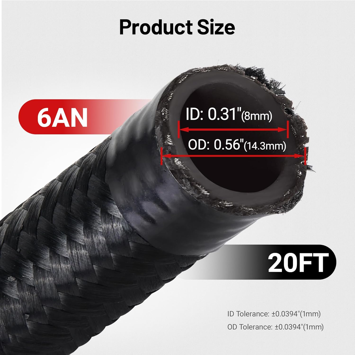
Image 4.1: Detailed view of the 6AN hose dimensions, including ID (0.31") and OD (0.56").
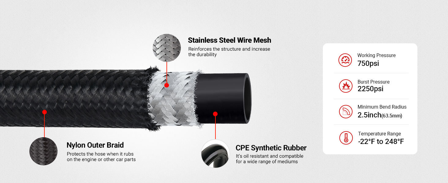
Image 4.2: Cross-section illustrating the hose construction: CPE synthetic rubber inner, stainless steel wire mesh, and nylon outer braid.

Image 4.3: Key performance parameters of the 6AN hose, including 750psi working pressure, 2250psi burst pressure, and a temperature range of -22°F to 248°F.
5. Fluid Compatibility
The EVIL ENERGY 6AN braided fuel hose is compatible with a wide range of automotive fluids:
- Transmission Fluid
- Engine Oil
- Race Gas
- Vacuum
- Hydraulic Fluid
- Diesel Fuel
- Standard Automotive Fuel
- Coolant
Important Note: This hose is NOT compatible with E85, E10, or methanol fuels.

Image 5.1: Examples of compatible mediums for the fuel line, including diesel, E15 gasoline, antifreeze, and various lubricants.
6. Installation Instructions
Follow these steps for proper assembly and installation of the 6AN fuel line kit:
6.1. Hose Preparation and Cutting
- Measure the required length of the hose carefully.
- Wrap the cutting area of the hose tightly with electrical tape to prevent fraying of the nylon braid.
- Using a sharp hose cutter or fine-tooth saw, cut the hose squarely through the taped section. Ensure a clean, straight cut.
- Remove the tape and clean any debris from the cut end.
6.2. Fitting Assembly
- Unscrew the fitting's socket (outer nut) from the nipple (inner part).
- Insert the cut end of the hose into the socket. Push firmly until the hose bottoms out against the threads inside the socket.
- Apply a small amount of AN fitting lubricant or clean engine oil to the nipple threads.
- Carefully thread the nipple into the hose and socket assembly. Ensure the hose does not back out of the socket.
- Tighten the nipple into the socket using two AN wrenches (one to hold the socket, one to turn the nipple) until snug. Do not overtighten.
- Inspect the assembly for any exposed braid or improper seating.
6.3. Hose Separator Clamp Installation
- Position the hose separator clamps along the hose run where needed to maintain proper spacing and prevent rubbing.
- Secure the clamps using the provided hardware.

Image 6.1: Step-by-step visual guide for hose cutting, inserting the hose into the fitting socket, threading the nipple, and final assembly.

Image 6.2: Visual examples of the 6AN fuel line kit installed in different automotive engine compartments, demonstrating typical applications.
7. Operating Considerations
After installation, perform the following checks before operating the vehicle:
- Leak Check: With the engine off, cycle the ignition key to pressurize the fuel system (if applicable) and visually inspect all connections for any signs of leaks. For oil or coolant lines, start the engine and monitor for leaks.
- Clearance Check: Ensure the hose and fittings do not rub against any moving parts, sharp edges, or hot components. Adjust routing as necessary.
- Secure Mounting: Confirm all hose separator clamps and mounting points are secure.
During initial operation, periodically check the lines for leaks or signs of wear, especially after the first few driving cycles.
8. Maintenance
Regular maintenance helps ensure the longevity and safe operation of your fuel line kit:
- Visual Inspection: Periodically inspect the entire length of the hose and all fittings for signs of wear, cracks, abrasions, or leaks. Pay close attention to areas near heat sources or moving parts.
- Cleanliness: Keep the hose and fittings clean from dirt, grime, and corrosive substances. Use a mild detergent and water if cleaning is necessary.
- Tightness Check: Occasionally check the tightness of the AN fittings. Do not overtighten.
- Hose Routing: Ensure the hose remains properly routed and secured by the separator clamps. Adjust if any shifting has occurred.
9. Troubleshooting
If you encounter issues with your EVIL ENERGY 6AN Fuel Line Kit, consider the following:
9.1. Leaks at Fittings
- Cause: Improper assembly, insufficient tightening, damaged threads, or incorrect hose cut.
- Solution: Disassemble the fitting, inspect threads for damage, ensure the hose is fully seated in the socket, re-lubricate threads, and reassemble, tightening to the recommended torque (snug, not excessive). If threads are damaged, replace the fitting.
9.2. Hose Fraying
- Cause: Improper cutting technique, rubbing against other components.
- Solution: Ensure proper cutting technique with tape. If fraying occurs during use, re-route the hose to prevent contact with abrasive surfaces or sharp edges. Use hose separator clamps to maintain clearance.
9.3. Restricted Flow
- Cause: Kinked hose, debris inside the line.
- Solution: Inspect the hose for kinks and re-route if necessary, ensuring the minimum bend radius is not exceeded. If debris is suspected, disconnect and flush the line.
10. Warranty and Support
EVIL ENERGY products are manufactured to high-quality standards. For warranty information, technical support, or assistance with any issues not covered in this manual, please contact EVIL ENERGY customer service through their official website or the retailer where the product was purchased. Please have your model number (KT01269AN6BK-HW) and purchase details available when contacting support.


