EPEVER Tracer6415AN
EPEVER Tracer-AN Series MPPT Solar Charge Controller User Manual
Model: Tracer6415AN | Brand: EPEVER
1. Introduction
The EPEVER Tracer-AN series MPPT Solar Charge Controller is an advanced, high-efficiency device designed to manage power flow from solar panels to batteries and loads. Utilizing Multi-Phase Synchronous Rectification Technology (MSRT) and an advanced Maximum Power Point Tracking (MPPT) control algorithm, this controller ensures optimal energy harvesting from your photovoltaic (PV) array.
It features a dual-core processor architecture and a common negative design, offering high response speed, reliability, and adherence to industrial standards. The controller automatically identifies 12V, 24V, 36V, and 48V DC system voltages and is compatible with various battery types, including Sealed, Gel, Flooded, and Lithium batteries.

Figure 1: Front view of the EPEVER Tracer-AN MPPT Solar Charge Controller. This image displays the device's main body, LCD screen, and control buttons, highlighting its compact and robust design.
2. Key Features
- Advanced MPPT Technology: Ensures ultra-fast tracking speed with efficiency no less than 99.5%, maximizing energy harvest from solar panels.
- High Conversion Efficiency: Maximum DC/DC transfer efficiency up to 98.6%, and full load efficiency up to 98%.
- Wide System Voltage Compatibility: Automatically identifies 12V/24V/36V/48V DC system voltages.
- Versatile Battery Support: Compatible with Sealed, Gel, Flooded, and Lithium batteries.
- Comprehensive Protection: Includes various electronic protections for overcharge, over-discharge, overload, short circuit, and reverse polarity.
- Communication Interface: Isolated RS485 interface with standard MODBUS communication protocol, supporting PC software, mobile APP, and MT-50 remote meter for monitoring and parameter settings.
- Parallel Functionality: Supports up to 8 units charging in parallel for expanded system capacity.
- Real-time Data: Provides real-time energy recording and statistical functions.
- Temperature Compensation: Built-in battery temperature compensation function for optimized charging.

Figure 2: Characteristics of the EPEVER Tracer-AN controller, highlighting its clear LCD display for easy monitoring and the high-efficiency heat dissipation aluminum alloy design for reliable operation.
3. Product Components Overview
Familiarize yourself with the various components and interfaces of your Tracer-AN series controller:

Figure 3: Detailed view of the EPEVER Tracer-AN controller with numbered components.
- Charging LED indicator: Indicates the charging status.
- SELECT button: Used to navigate through menu options.
- Fuse: Integrated fuse for protection.
- Grounding Terminal: For system grounding.
- Fault LED indicator: Indicates system faults or warnings.
- LCD: Liquid Crystal Display for displaying system parameters and status.
- ENTER button: Used to confirm selections or enter menus.
- RBVS Port: Remote Battery Voltage Sensor port.
- Utility/Generator relay ON: Relay output for utility or generator control.
- RS485 port (5VDC/200mA): Communication port for external devices.
- RTS Port: Remote Temperature Sensor port.
- Generator and load relay enable: Terminal for enabling generator and load relays.
- PV reverse polarity alarm indicator: LED indicator for PV reverse polarity.
- Load control relay: Relay for controlling the load output.
- Utility/Generator relay OFF: Relay output for utility or generator control.
- PV Terminals: Input terminals for solar panel connection.
- Battery Terminals: Terminals for battery bank connection.
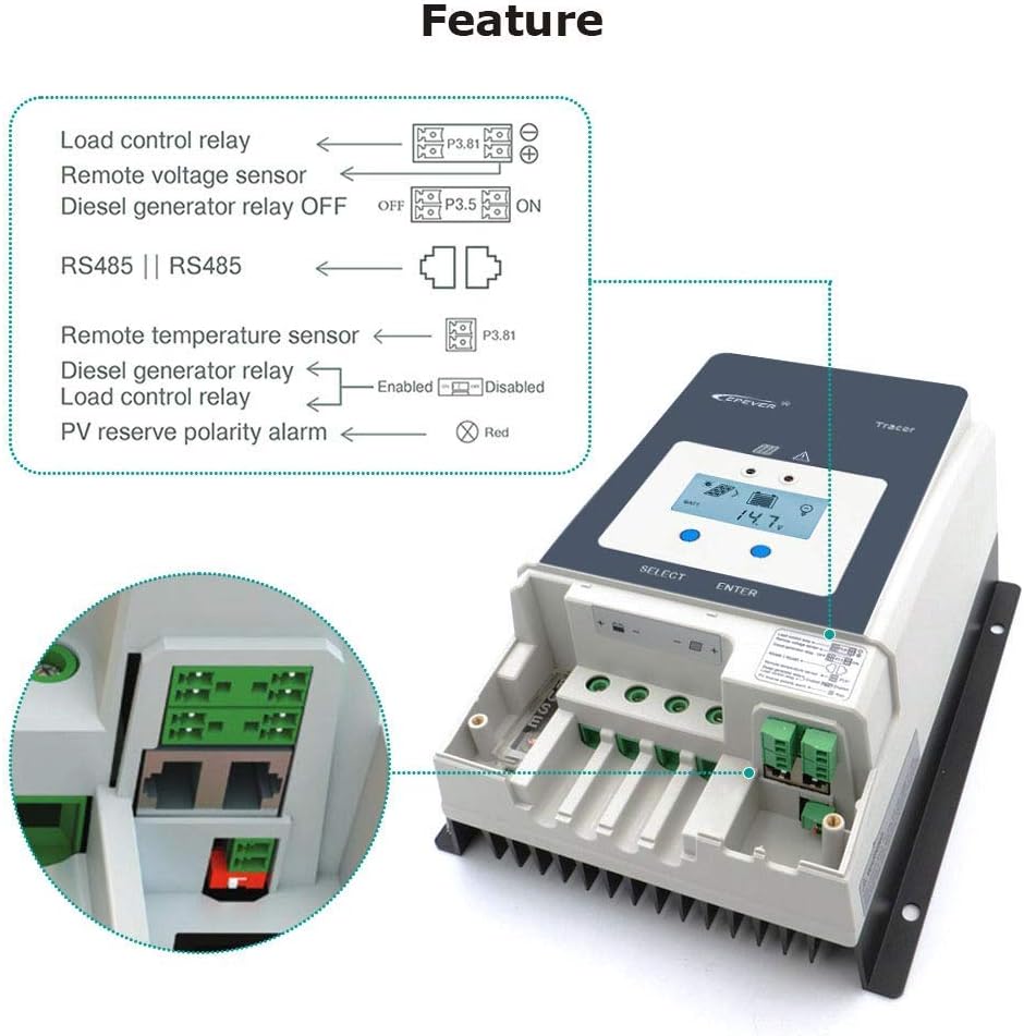
Figure 4: Diagram illustrating the various relay and sensor connections available on the Tracer-AN controller, including load control, remote voltage sensor, diesel generator relay, remote temperature sensor, and PV reverse polarity alarm.
4. Setup and Installation
Proper installation is crucial for the safe and efficient operation of your solar charge controller. Please follow these steps carefully:
- Safety First: Before wiring, ensure all power sources (solar panels, batteries) are disconnected. Do not close the circuit breaker or fuse until all connections are complete.
- Mounting: Mount the controller vertically on a flat, non-flammable surface in a well-ventilated area, away from direct sunlight, high temperatures, and moisture. Ensure adequate clearance around the controller for heat dissipation.
- Battery Connection: Connect the battery cables to the controller's battery terminals (17) first. Ensure correct polarity (+ to + and - to -). It is highly recommended to install a fuse (1.25 to 2 times the rated current of the controller) on the battery side, no more than 150mm from the battery.
- PV Array Connection: Connect the solar panel cables to the controller's PV terminals (16). Ensure correct polarity. The PV reverse polarity alarm indicator (13) will alert you if connected incorrectly.
- Load Connection (Optional): If using the load output, connect your DC load to the designated load terminals. Note that this model primarily focuses on battery charging and may not have direct load terminals for power output. If an inverter is to be connected, connect it directly to the battery, not to the load side of the controller.
- Grounding: Connect the grounding terminal (4) to an earth ground.
- Optional Connections:
- Remote Temperature Sensor (RTS): Connect the RTS to the RTS Port (11) for accurate battery temperature compensation.
- Remote Battery Voltage Sensor (RBVS): Connect the RBVS to the RBVS Port (8) for precise battery voltage measurement.
- Communication: Connect the RS485 port (10) to a PC, MT-50 remote meter, or other monitoring devices using the appropriate cable.
- Power On: Once all connections are secure and verified, close the battery circuit breaker/fuse, then the PV array circuit breaker. The controller will power on and begin operation.

Figure 5: Comprehensive wiring diagram for the EPEVER Tracer-AN controller, illustrating connections for solar panels (PV), batteries, and various loads including an inverter, computer, speakers, fan, and TV. This diagram emphasizes the correct sequence and polarity for system integration.
5. Operating Instructions
The Tracer-AN controller is designed for user-friendly operation via its LCD display and buttons, as well as external monitoring tools.
5.1. LCD Display and Buttons
The LCD (6) provides real-time system status and parameters. Use the SELECT button (2) to cycle through different display screens and the ENTER button (7) to confirm settings or enter sub-menus.
- Main Display: Shows battery voltage, charging current, PV voltage, and other key metrics.
- Parameter Settings: Access menus to set battery type, charging parameters, load control modes, and more. Refer to the detailed manual for specific menu navigation.
5.2. Battery Type Selection
It is critical to set the correct battery type for optimal charging and battery longevity. The controller supports Sealed, Gel, Flooded, and Lithium batteries. This setting can typically be adjusted via the LCD menu or through the PC software/APP.
5.3. Monitoring and Communication
The controller offers multiple ways to monitor your solar system:
- MT-50 Remote Meter: A dedicated remote display unit that connects via the RS485 port, providing a convenient way to monitor and configure the controller from a distance.
- PC Software: EPEVER provides PC software that allows for detailed monitoring, data logging, and advanced parameter configuration. Connect via the RS485 port using a suitable communication cable.
- Mobile APP: A mobile application is available for smartphones, offering remote monitoring and control capabilities via Bluetooth or Wi-Fi modules (sold separately) connected to the RS485 port.
6. Maintenance
Regular maintenance ensures the longevity and optimal performance of your EPEVER Tracer-AN solar charge controller.
- Visual Inspection: Periodically inspect the controller and all connections for any signs of damage, corrosion, loose wiring, or overheating.
- Cleanliness: Keep the controller clean and free from dust, dirt, and debris. Use a dry cloth to wipe the surface. Ensure the heat sink fins are not obstructed to allow for proper heat dissipation.
- Terminal Tightness: Check all terminal connections (battery, PV, load, communication) for tightness. Loose connections can cause resistance, heat buildup, and performance degradation.
- Battery Health: Monitor your battery bank's health regularly. Ensure batteries are properly maintained according to their manufacturer's guidelines. Incorrect battery voltage or synchronization issues can affect controller performance.
- Environmental Conditions: Ensure the installation environment remains within the specified operating temperature range and is free from excessive moisture or corrosive gases.
7. Troubleshooting
This section provides solutions to common issues you might encounter with your Tracer-AN controller. For more complex problems, consult the full product manual or contact EPEVER support.
| Problem | Possible Cause | Solution |
|---|---|---|
| Controller not powering on / LCD blank | No battery connection or reverse polarity; Battery voltage too low. | Check battery connections and polarity. Ensure battery voltage is above the minimum operating voltage. |
| No charging / Low charging current | PV array not connected or reverse polarity; PV voltage too low; Overcast weather; Battery full. | Check PV connections and polarity. Ensure PV voltage is within range. Wait for better sunlight. Controller stops charging when battery is full. |
| Controller shuts down unexpectedly | Over-temperature; Overload; Battery voltage issues (e.g., out of sync cells in a bank). | Ensure proper ventilation. Reduce load. Check battery health and balance, especially in multi-battery systems. |
| PC software/APP connection issues | Incorrect communication cable; Driver issues; Software configuration. | Ensure you are using the correct EPEVER communication cable. Install/reinstall necessary drivers. Verify software settings and COM port selection. |
| Fault LED indicator is on | System fault (e.g., over-voltage, short circuit, high temperature). | Refer to the LCD display for specific error codes or the full manual's fault code section to identify and resolve the issue. |
8. Technical Specifications
Below are the key technical specifications for the EPEVER Tracer-AN series, specifically for the Tracer6415AN model, and general series parameters.
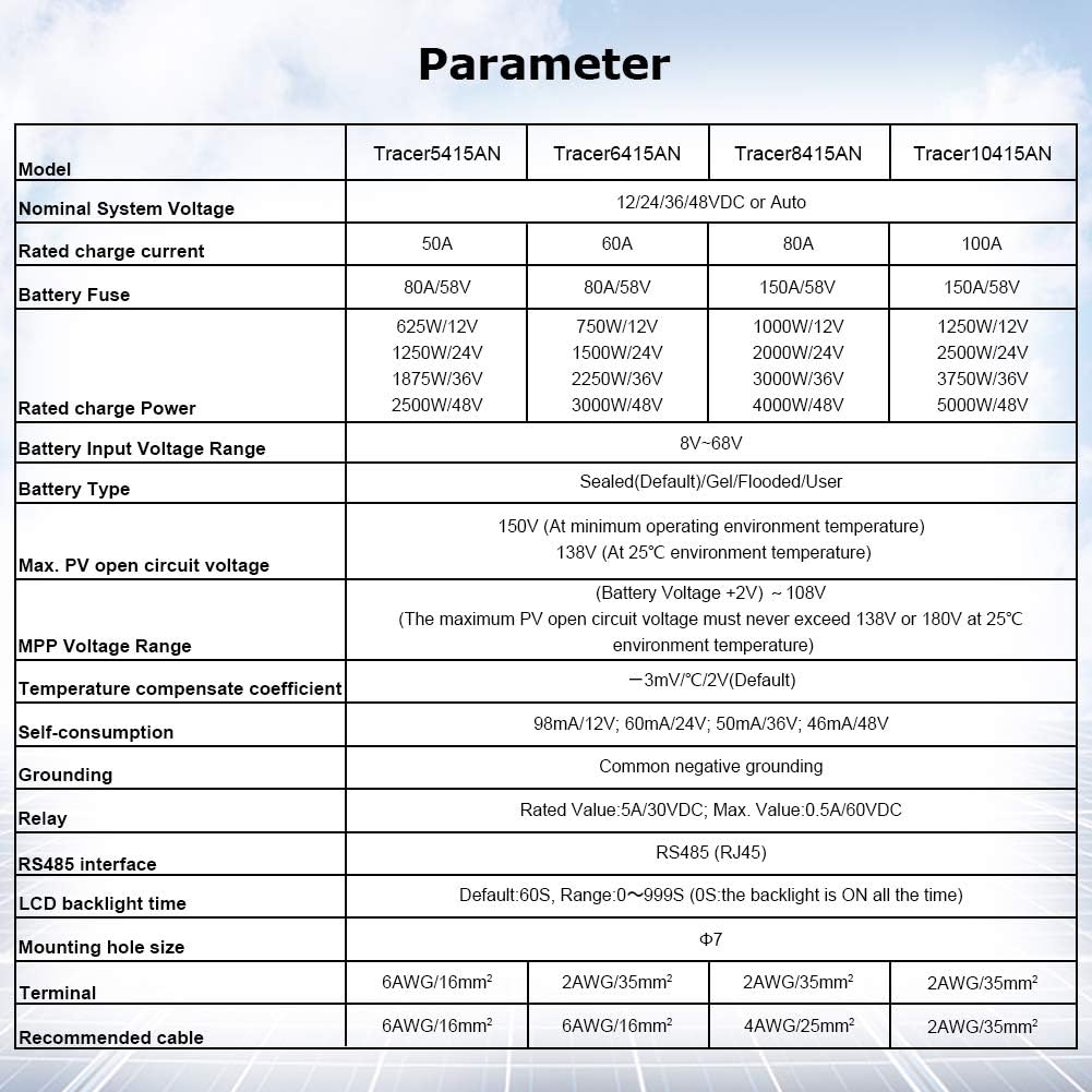
Figure 6: Detailed parameter table for EPEVER Tracer-AN series models, including Tracer5415AN, Tracer6415AN, Tracer8415AN, and Tracer10415AN, outlining nominal system voltage, rated charge current, PV input power, battery types, and other electrical and mechanical specifications.
| Parameter | Value (Tracer6415AN) |
|---|---|
| Nominal System Voltage | 12/24/36/48VDC or Auto |
| Rated Charge Current | 60A |
| Rated Charge Power | 750W/12V; 1500W/24V; 2250W/36V; 3000W/48V |
| Max. PV Open Circuit Voltage | 150V (at minimum operating environment temperature) |
| MPP Voltage Range | (Battery Voltage +2V) ~ 108V |
| Battery Type | Sealed(Default)/Gel/Flooded/User |
| Self-consumption | 98mA/12V; 60mA/24V; 50mA/36V; 46mA/48V |
| Grounding | Common negative grounding |
| RS485 Interface | RS485 (RJ45) |
| Package Dimensions | 17.2 x 11.6 x 7.6 inches |
| Item Weight | 11.88 pounds |
| UPC | 732376583589 |

Figure 7: Dimensions of the EPEVER Tracer-AN controller, showing its length (L 261mm), width (W 216mm), and height (H 119mm) for installation planning.
9. Warranty and Support
EPEVER products are designed for reliability and performance. For specific warranty terms and conditions, please refer to the warranty card included with your product or visit the official EPEVER website. Typically, EPEVER offers a standard warranty period for their solar charge controllers covering manufacturing defects.
For technical support, troubleshooting assistance, or inquiries regarding your Tracer-AN series controller, please contact EPEVER customer service. You can often find contact information on the official EPEVER website or through the retailer where you purchased the product.
You can also visit the EPEVER Store on Amazon for additional resources and product information.
10. Typical Applications
The EPEVER Tracer-AN series MPPT solar charge controller is highly versatile and suitable for a wide range of solar power applications, including but not limited to:
- Off-grid Residential Systems: Powering homes or cabins not connected to the main grid.
- RV and Marine Systems: Providing reliable power for recreational vehicles and boats.
- Remote Monitoring Stations: Ideal for telecommunications, environmental monitoring, and security systems in remote locations.
- Solar Street Lighting: Efficiently managing power for standalone street lights.
- Small Commercial Systems: Supporting various small-scale commercial power needs.

Figure 8: Examples of typical applications for the EPEVER Tracer-AN solar charge controller, including residential rooftop solar installations, solar street lights, and large-scale solar arrays, demonstrating its adaptability across various solar power setups.
Ask a question about this manual
Ask about setup, troubleshooting, compatibility, parts, safety, or missing instructions. Manuals+ will review the question and use this page’s manual context to help answer it.