1. Introduction
Welcome to the instruction manual for your FMS A-10 Thunderbolt II V2 Remote Control Airplane. This model is a 6-channel, twin 70mm ducted fan (EDF) aircraft designed for enthusiasts. This manual provides essential information for the safe assembly, operation, and maintenance of your RC plane. Please read this manual thoroughly before operating the aircraft to ensure proper function and safety.
This is a Plug and Play (PNP) version, meaning it comes with pre-installed ESCs, motors, and servos. A remote control (radio), battery, and charger are not included and must be purchased separately.

Figure 1: The FMS A-10 Thunderbolt II V2 RC Plane in an aerial view.
2. Safety Information
Operating remote control aircraft requires caution and adherence to safety guidelines. Failure to follow these instructions may result in injury or damage to property.
- Age Recommendation: This product is recommended for users aged 14 years and up.
- Read the Manual: Always read and understand the entire instruction manual before assembly or operation.
- Flight Area: Operate the aircraft in open areas, away from people, buildings, trees, and power lines. Avoid flying near airports or restricted airspace.
- Weather Conditions: Do not fly in strong winds, rain, or other adverse weather conditions.
- Pre-Flight Check: Always perform a thorough pre-flight check, including battery charge, control surface movement, and radio range.
- Battery Safety: Handle LiPo batteries with extreme care. Always charge them using a compatible charger in a fire-safe location. Never overcharge or discharge LiPo batteries.
- Propeller/Fan Safety: Keep hands, face, and loose clothing away from the rotating ducted fans.
- Respect Others: Be mindful of others in your flying area.
3. Product Overview and Features
The FMS A-10 Thunderbolt II V2 is an advanced RC jet model featuring significant enhancements over its predecessor. Key features include:
- Power System: Equipped with dual 70mm 12-blade ducted fans and upgraded dual 80A Electronic Speed Controllers (ESCs) with an external 8A BEC for reliable performance.
- Servos: Elevator and rudder control surfaces utilize upgraded 23g metal geared servos for increased torque and precision.
- Landing Gear: Precision-designed nose landing gear minimizes play, ensuring straight tracking. The tires are made from an improved, more durable compound for extended service life. Electronic retracts include over-current protection.
- Connectors: Features a 'soft' connector design for the wing quick-release system, enhancing reliability.
- Control Authority: Increased elevator travel provides pilots with more precise control.
- Canopy Latch: A robust canopy latch with an extended pin reduces the possibility of accidental release during flight.
- Battery Bay: Enlarged battery bay designed to accommodate two 6S 3300mAh LiPo batteries for extended flight times.
- Scale Details: Highly realistic scale features including rivets, panel lines, removable bombs and rocket pods, a scale pilot figure, and an ultra-bright LED light system.
4. Setup and Assembly
The FMS A-10 V2 features a screw-together airframe for straightforward assembly. Follow these general steps:
- Unpacking: Carefully remove all components from the packaging. Inspect for any damage during shipping.
- Wing Assembly: Attach the main wings to the fuselage. Ensure all electrical connections for the wings (servos, lights) are securely made using the 'soft' connector system.
- Tail Assembly: Secure the horizontal and vertical stabilizers. Connect the elevator and rudder control rods to the respective servos using the ball-linked control surfaces.
- Landing Gear: Verify the electronic retracts and nose landing gear are functioning correctly.
- Ordnance (Optional): Attach the removable bombs and rocket pods as desired.
- Receiver Installation: Install your chosen RC receiver in the designated compartment. Ensure all servo leads and ESC leads are correctly connected to the receiver.
- Battery Placement: Position your LiPo batteries (two 6S 3300mAh recommended) in the enlarged battery bay. Secure them to prevent shifting during flight.
- Center of Gravity (CG): Refer to the specific manual included with your product for the recommended Center of Gravity (CG) location. Adjust battery position as needed to achieve the correct CG.

Figure 2: Front view of the FMS A-10 V2 on the runway, ready for flight.

Figure 3: Rear view of the FMS A-10 V2 on the runway, highlighting the twin ducted fans.
5. Operating Instructions
Before your first flight, ensure all safety checks are completed and you are familiar with your radio transmitter's controls.
5.1 Pre-Flight Checks
- Battery: Ensure flight batteries are fully charged and securely installed.
- Control Surfaces: Verify that all control surfaces (ailerons, elevator, rudder) move freely and in the correct direction relative to your transmitter inputs.
- Motor/Fan Test: Briefly test the ducted fans at low throttle to confirm proper rotation and sound. Keep clear of the fan intakes and exhausts.
- Radio Range: Perform a range check of your radio system according to your transmitter's manual.
- Landing Gear: Confirm the retracts extend and retract smoothly.
5.2 Takeoff
Place the aircraft on a smooth, level surface facing into the wind. Gradually increase throttle while maintaining directional control with the rudder. Once sufficient speed is gained, gently apply up elevator to lift off.
5.3 Flight
Maintain a safe altitude and distance. Practice gentle turns and maneuvers. Monitor your flight time to ensure you have enough battery capacity for a safe landing.

Figure 4: The FMS A-10 V2 in a stable flight pattern.

Figure 5: Top view of the FMS A-10 V2 during flight.
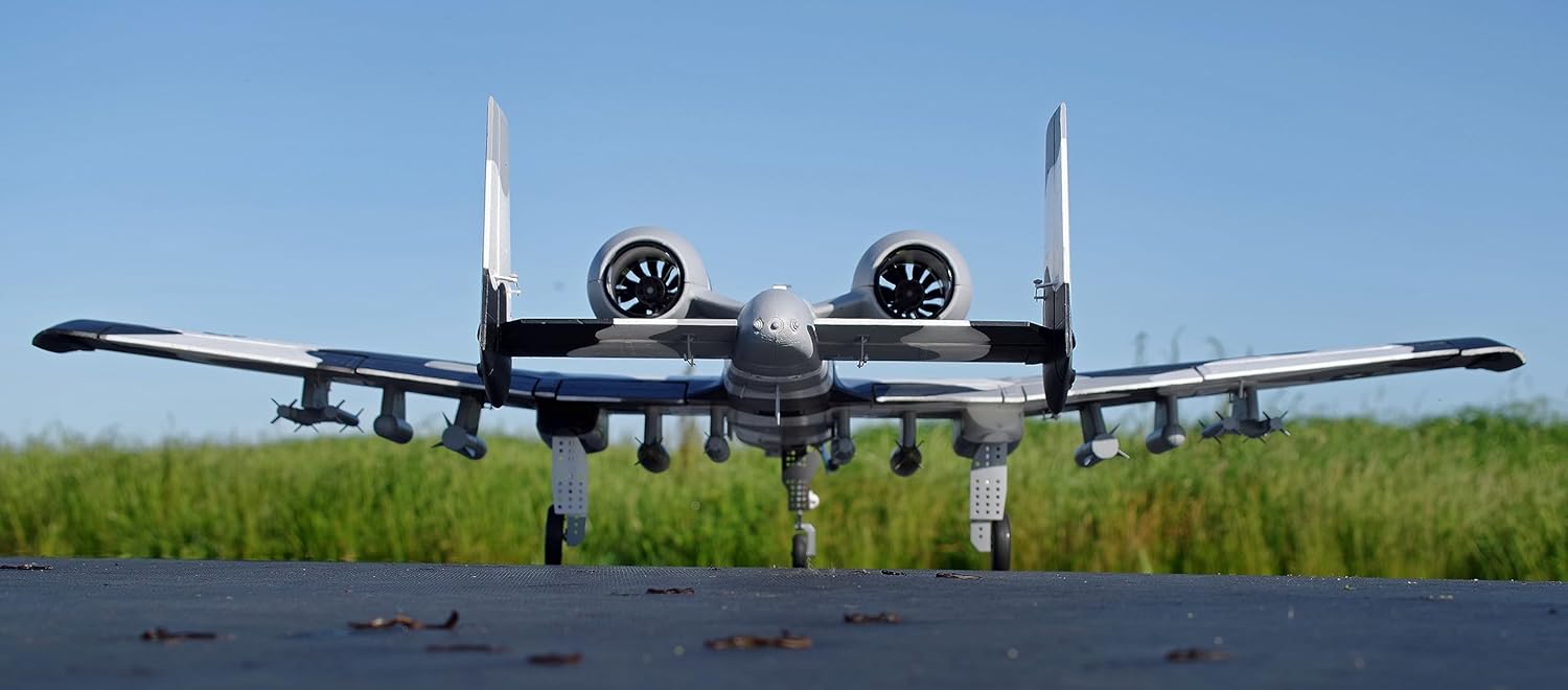
Figure 6: Bottom view of the FMS A-10 V2 during flight, highlighting the twin EDF units.
5.4 Landing
Reduce throttle and deploy landing gear. Approach the runway at a controlled speed, maintaining a gentle descent. Flare gently just above the runway and reduce throttle completely for a smooth touchdown. Maintain directional control until the aircraft comes to a complete stop.

Figure 7: The FMS A-10 V2 on final approach for landing.
6. Maintenance
Regular maintenance ensures the longevity and safe operation of your FMS A-10 V2.
- Post-Flight Inspection: After each flight, inspect the airframe for any damage, cracks, or loose components.
- Control Surfaces: Check all control surfaces and linkages for free movement and secure connections. Ensure no slop in the ball-linked control surfaces.
- Landing Gear: Inspect the landing gear for damage or bending. Check the durability of the tires and replace if worn.
- Motors/Fans: Ensure the ducted fans are free of debris and rotate smoothly. Check for any unusual noises during operation.
- Electrical Connections: Verify all electrical connections, especially the wing quick-release system, are secure and free from corrosion or damage.
- Cleaning: Clean the aircraft with a soft, dry cloth. Avoid using harsh chemicals that could damage the foam or paint.
- Storage: Store the aircraft in a cool, dry place, away from direct sunlight and extreme temperatures. Remove batteries before storage.
7. Troubleshooting
This section addresses common issues you might encounter.
| Problem | Possible Cause | Solution |
|---|---|---|
| Aircraft does not respond to controls | Unbound receiver, low transmitter/receiver battery, incorrect wiring. | Ensure receiver is bound to transmitter. Check all battery levels. Verify all servo and ESC connections to the receiver. |
| Motors not spinning or unevenly | ESC not armed, motor/ESC connection issue, damaged motor/ESC. | Ensure throttle is at zero when connecting battery. Check all motor-to-ESC and ESC-to-receiver connections. Inspect motors and ESCs for visible damage. |
| Landing gear not retracting/extending | Loose connection, damaged retract unit, insufficient power. | Check wiring to retracts. Inspect retract units for damage. Ensure flight battery is adequately charged. |
| Aircraft flies erratically | Incorrect CG, control surface trim, damaged control surface/servo. | Verify CG is correct. Adjust trims on transmitter. Inspect control surfaces and servos for damage or excessive play. |
| Battery bay too small for stated batteries | Manufacturing variance or specific battery dimensions. | Carefully check battery dimensions against the bay. Consider alternative battery sizes that fit securely. |
8. Specifications
Key technical specifications for the FMS A-10 Thunderbolt II V2 RC Plane:
- Model: A-10 Thunderbolt II V2
- Brand: FMS
- Channels: 6 Channel
- Power System: Twin 70mm Ducted Fan (EDF), 12-Blade
- ESCs: Dual 80A with external 8A BEC
- Servos: 23g metal geared for Elevator and Rudder (as per product description)
- Recommended Battery: Two 6S 3300mAh LiPo (PNP version, not included)
- Assembly: Screw-together airframe
- Landing Gear: Electronic retracts with over-current protection, improved durable tires
- Recommended Age: 14 years and up
9. Warranty and Support
FMS is committed to customer satisfaction. If you encounter any issues with your product, please contact the seller or manufacturer directly for assistance.
- Product Issues: For any concerns regarding the quality or function of your FMS A-10 Thunderbolt II V2, please reach out to the point of purchase or FMS customer service.
- Returns: Standard return policies typically allow for a refund or replacement within 30 days of purchase for eligible items. Refer to your retailer's specific return policy.
- Damaged/Incorrect Product: If your package arrived damaged or you received the wrong product, retain all packaging materials and contact customer service immediately with photographic evidence.


