
Hantek HT25COP
Contents
Hantek HT25COP Ignition Waveform Probe User Manual
Model: HT25COP
1. Introduction
The Hantek HT25COP is a specialized probe designed for measuring ignition waveforms of automobile engine coil-on-plug (COP) systems. It allows for direct measurement on the ignition coil without the need for extension cables, providing accurate signal acquisition for diagnostic purposes when used with a compatible oscilloscope.

Image 1.1: Hantek HT25COP Ignition Waveform Probe with its protective sleeve and packaging.
2. Key Features
- Direct Measurement: Enables direct measurement on the ignition coil, eliminating the need for additional extension cables.
- Oscilloscope Compatibility: Designed to work with standard oscilloscopes. Note: May not be suitable for all 4-wired COP coils due to shielding.
- Anti-interference Design: Features special anti-interference design for high accuracy measurements.
- Ergonomic Design: The probe is ergonomically designed and can be arbitrarily curved for ease of use in various engine bay configurations.
- Integrated LED Light: Includes a highlight LED for convenient operation in low-light or dark conditions.
3. What's in the Box
The Hantek HT25COP set includes:
- 1 x Hantek HT25COP Ignition Waveform Probe
4. Setup Instructions
- Connect to Oscilloscope: Connect the BNC cable end of the HT25COP probe to an input channel on your oscilloscope.
- Power On: Ensure your oscilloscope is powered on and configured for appropriate voltage and time base settings. A typical setting for initial signal acquisition might be 100mV/div and 1.0ms/div, adjusting as needed. For shielded coils, an oscilloscope capable of 5mV/div or lower may be required for clear signal pickup.
- Prepare Vehicle: Ensure the vehicle's engine is in a safe operating condition for testing.

Image 4.1: Diagram illustrating the components of the HT25COP probe, including the COP ignition signal receiver, LED light, ergonomic handle, and BNC cable.
5. Operating Instructions
- Position the Probe: Carefully place the COP ignition signal receiver end of the HT25COP probe directly onto the coil-on-plug unit of the engine cylinder you wish to test. The flexible probe design allows for easy positioning.
- Activate LED (if needed): If working in a dark environment, press the button on the probe handle to activate the highlight LED for better visibility.
- Observe Waveform: Monitor the oscilloscope display for the ignition waveform. The probe detects the magnetic field generated by the ignition coil.
- Analyze Waveform: A typical ignition waveform will show key characteristics such as breakdown voltage, spark initial voltage, primary closure, and spark time. Analyze these parameters to diagnose ignition system performance.

Image 5.1: The Hantek HT25COP probe being used to measure an ignition waveform on a vehicle engine, connected to an oscilloscope.
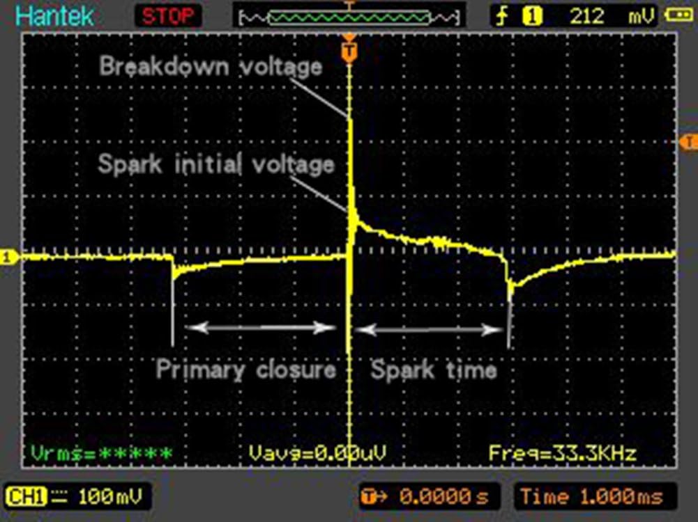
Image 5.2: Example of an ignition waveform displayed on an oscilloscope, highlighting key diagnostic points like breakdown voltage and spark time.
6. Maintenance
- Cleaning: Wipe the probe clean with a soft, dry cloth after each use. Avoid using harsh chemicals or abrasive materials.
- Storage: Store the probe in its protective sleeve in a dry, cool place away from direct sunlight and extreme temperatures.
- Inspection: Periodically inspect the cable and probe tip for any signs of wear or damage. Do not use if damaged.
7. Troubleshooting
- No or Weak Signal on Oscilloscope:
-
- Check Probe Placement: Ensure the probe is correctly positioned directly on the coil-on-plug unit.
- Oscilloscope Sensitivity: Verify that your oscilloscope's vertical sensitivity (mV/div) is set appropriately. For some heavily shielded coils, a setting of 5mV/div or lower may be necessary to pick up a clear signal.
- Coil Shielding: Be aware that some coil-on-plug systems, particularly 3-wire or 4-wire configurations, may have heavy internal shielding that can significantly distort or prevent signal acquisition with paddle-type probes. The HT25COP is most effective on 2-wire COP setups.
- Oscilloscope Functionality: Confirm that your oscilloscope is functioning correctly and its input channel is active.
- Distorted Waveform:
-
- External Interference: Ensure there are no strong electromagnetic interference sources nearby.
- Probe Contact: Confirm good contact between the probe and the COP unit.
- Coil Type: As mentioned, heavily shielded 3-wire or 4-wire COP systems can inherently produce distorted signals with this type of probe.
8. Specifications
| Attribute | Value |
|---|---|
| Brand | Hantek |
| Model | HT25COP |
| Item Weight | 9.6 ounces |
| Item Dimensions (L x W x H) | 17 x 2 x 2.5 inches |
| Unit Count | 1 Count |
| Compatible Devices | Oscilloscope (except some 4-wired COP coils) |
| Part Number | HT25COP |
9. Warranty Information
The manufacturer states that there is no explicit warranty description provided for this product.
10. Support
For technical support or further inquiries, please refer to the official Hantek website or contact your product retailer. Keep your purchase receipt and product model number (HT25COP) handy for any support requests.
Official Hantek Store: Visit Hantek Store on Amazon
Ask a question about this manual
Ask about setup, troubleshooting, compatibility, parts, safety, or missing instructions. Manuals+ will review the question and use this page’s manual context to help answer it.