1. Introduction
The Walfront UT219DS is a professional digital clamp meter designed for accurate and reliable electrical measurements. It is an essential tool for electrical maintenance personnel, HVAC technicians, and anyone requiring precise measurements of AC/DC current, AC/DC voltage, resistance, capacitance, frequency, temperature, and diode testing. This manual provides detailed instructions for the safe and effective use of your UT219DS clamp meter.
2. Safety Information
WARNING: To avoid possible electric shock, fire, or personal injury, please read all safety information before using the product.
- Always adhere to local and national safety codes.
- Do not use the meter if it appears damaged or if the test leads are damaged.
- Verify the meter's operation on a known voltage source before use.
- Do not apply more than the rated voltage, as marked on the meter, between the terminals or between any terminal and earth ground.
- Use caution with voltages above 30V AC RMS, 42V peak, or 60V DC. These voltages pose a shock hazard.
- Keep fingers behind the finger guards on the test probes during use.
- Replace the batteries when the low battery indicator appears to ensure accurate readings.
- Do not operate the meter in explosive gas, vapor, or dusty environments.
- Ensure the rotary switch is in the correct position for the desired measurement before connecting to the circuit.
- When measuring current, ensure the circuit is de-energized before clamping the jaw around the conductor.
3. Product Overview
The Walfront UT219DS Digital Clamp Meter is designed for robust performance and ease of use. It features a large LCD display, a durable clamp jaw, and a rotary dial for function selection.
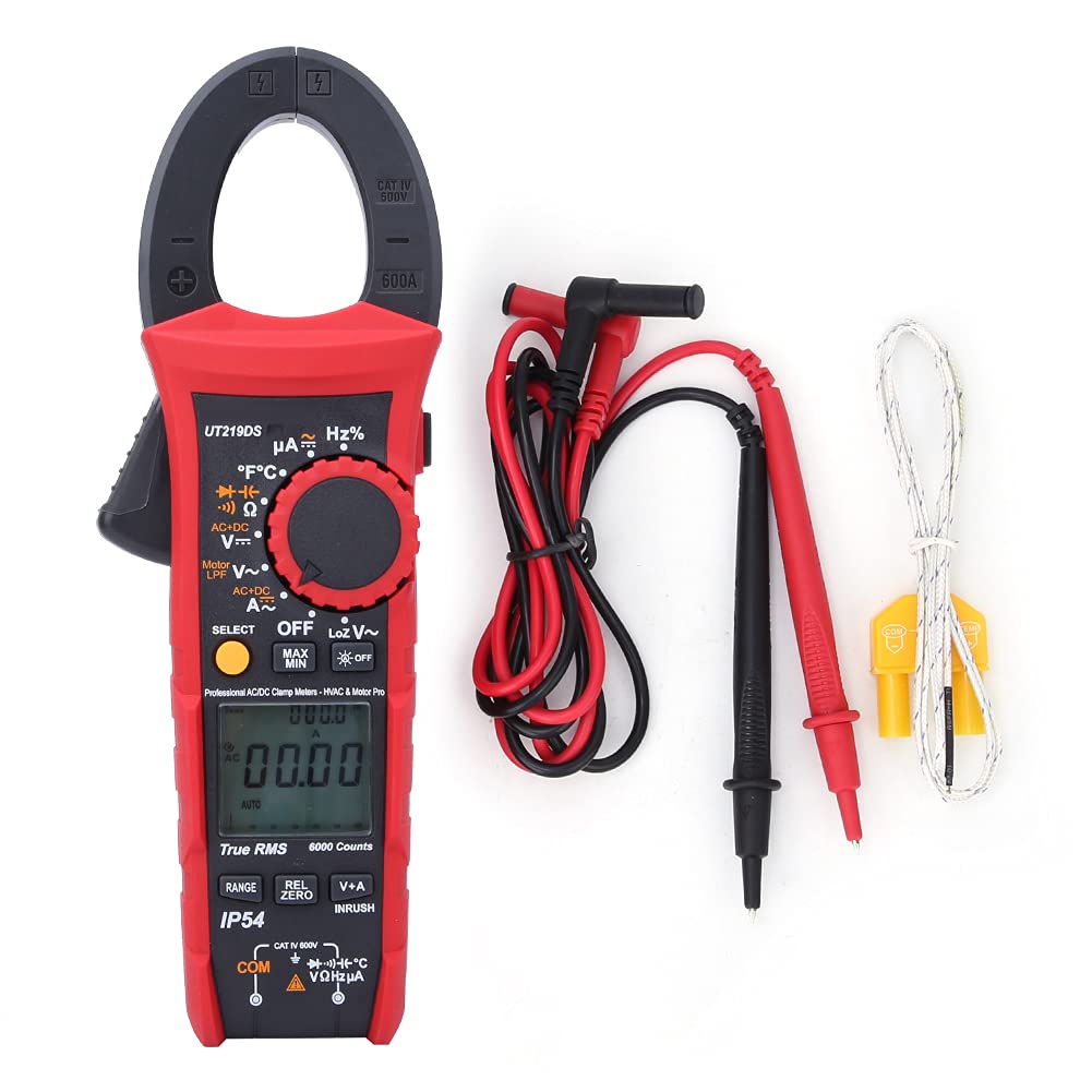
Figure 3.1: The Walfront UT219DS Digital Clamp Meter, including the main unit, red and black test leads, and a K-type temperature probe.
Key Features:
- 6000 Counts LCD Display: Provides clear and precise readings.
- True RMS Measurement: Ensures accurate readings for non-sinusoidal waveforms.
- 33mm Jaw Opening: Allows for easy clamping around conductors without interrupting the circuit.
- IP54 Rating: Offers protection against dust and splashing water.
- 2-Meter Drop Test: Designed for durability in demanding environments.
- Automatic Backlight: Enhances visibility in low-light conditions.
- Auto Power Off: Conserves battery life.
- Special Functions: Includes LoZ voltage, Motor Phase Sequence, Low-Pass Filter (LPF), Inrush current, Data Hold, MAX/MIN, Relative Value, and Dual Display (V+A).

Figure 3.2: The ergonomic design of the UT219DS allows for comfortable single-hand operation.
Components:
- Clamp Jaw: Used for non-contact AC/DC current measurement.
- Rotary Dial: Selects measurement functions.
- LCD Display: Shows measurement readings, units, and function indicators.
- Function Buttons: (SELECT, MAX/MIN, REL/ZERO, V+A, INRUSH) for additional features.
- Input Terminals: For connecting test leads and temperature probe.
- Trigger: Opens the clamp jaw.

Figure 3.3: Detailed view of the clamp jaw mechanism and the input jacks for test leads and probes.
4. Setup
Battery Installation:
The UT219DS requires three (3) 1.5V AAA alkaline batteries for operation. Follow these steps to install or replace the batteries:
- Ensure the meter is powered off and disconnect all test leads from the meter and any circuit.
- Locate the battery compartment cover on the back of the meter.
- Use a screwdriver to loosen the screw(s) securing the battery cover.
- Remove the battery cover.
- Insert three new 1.5V AAA alkaline batteries, observing the correct polarity (+ and -) as indicated inside the compartment.
- Replace the battery cover and tighten the screw(s) securely.

Figure 4.1: Rear view of the meter with the battery compartment open, illustrating the placement for three AAA batteries.
5. Operating Instructions
Before taking any measurements, ensure the meter is set to the correct function and the test leads are properly connected.
5.1 Function Selection
Turn the rotary dial to select the desired measurement function. The meter will automatically select the appropriate range for most functions (Auto Range). Press the SELECT button to toggle between different sub-functions within a single dial position (e.g., AC/DC voltage, resistance/continuity/diode).
5.2 AC/DC Current Measurement (Clamp Jaw)
- Turn the rotary dial to the A~ (AC Current) or A= (DC Current) position.
- Press the trigger to open the clamp jaw.
- Enclose only one conductor of the circuit within the clamp jaw. For AC current, ensure the conductor is centered. For DC current, observe polarity.
- Read the current value on the LCD display.
5.3 AC/DC Voltage Measurement
- Insert the red test lead into the VΩHz terminal and the black test lead into the COM terminal.
- Turn the rotary dial to the V~ (AC Voltage) or V= (DC Voltage) position. Use the SELECT button to switch between AC and DC if needed.
- Connect the test probes across the circuit or component to be measured.
- Read the voltage value on the LCD display.
5.4 Resistance, Continuity, Diode, and Capacitance Measurement
- Insert the red test lead into the VΩHz terminal and the black test lead into the COM terminal.
- Turn the rotary dial to the Ω (Resistance/Continuity/Diode/Capacitance) position.
- Press the SELECT button to cycle through Resistance (Ω), Continuity ()))), Diode (->|), and Capacitance (F) functions.
- Connect the test probes across the component to be measured. For continuity, a beep indicates a continuous circuit. For diode, forward voltage drop is displayed. For capacitance, ensure the capacitor is discharged before measurement.
- Read the value on the LCD display.
5.5 Frequency/Duty Cycle Measurement (Hz%)
- Insert the red test lead into the VΩHz terminal and the black test lead into the COM terminal.
- Turn the rotary dial to the Hz% position.
- Connect the test probes across the circuit where frequency or duty cycle is to be measured.
- Read the frequency (Hz) or duty cycle (%) value on the LCD display.
5.6 Temperature Measurement
- Turn the rotary dial to the °C°F position.
- Insert the K-type temperature probe into the input terminals, observing polarity.
- Place the tip of the temperature probe on the object or in the environment to be measured.
- Read the temperature value in Celsius or Fahrenheit on the LCD display. Use the SELECT button to switch between units.
5.7 LoZ Voltage Measurement
The LoZ (Low Impedance) voltage measurement function provides a low input impedance to eliminate ghost voltages, ensuring more accurate readings in certain applications.
- Insert the red test lead into the VΩHz terminal and the black test lead into the COM terminal.
- Turn the rotary dial to the LoZ V~ position.
- Connect the test probes across the circuit to be measured.
- Read the LoZ voltage value on the LCD display.
5.8 Motor Phase Sequence Measurement
This function helps identify the phase sequence of a three-phase motor or power supply.
- Insert the test leads into the appropriate terminals as indicated for voltage measurement.
- Turn the rotary dial to the Motor LPF V~ position.
- Follow the on-screen prompts or specific instructions for connecting the probes to the three phases.
- The display will indicate the phase sequence.
5.9 Low-Pass Filter (LPF) Measurement
The LPF function filters out high-frequency noise, providing stable and accurate voltage and frequency measurements for variable frequency drives (VFDs) and other noisy environments.
- Insert the test leads into the appropriate terminals for voltage measurement.
- Turn the rotary dial to the Motor LPF V~ position.
- Connect the test probes across the circuit.
- The meter will display the filtered voltage or frequency.
5.10 Inrush Current Measurement
This function measures the initial surge of current when a motor or other inductive load starts up.
- Turn the rotary dial to an AC Current (A~) position.
- Press the INRUSH button. The meter will enter inrush measurement mode.
- Clamp the jaw around the single conductor of the motor or load.
- Start the motor/load. The meter will capture and display the peak inrush current.
5.11 Data Hold (H)
Press the H button to freeze the current reading on the display. Press it again to release.
5.12 Maximum/Minimum (MAX/MIN)
Press the MAX/MIN button to record the maximum and minimum readings over time. Press again to cycle between MAX, MIN, and current reading. Hold to exit.
5.13 Relative Value (REL/ZERO)
Press the REL/ZERO button to store the current reading as a reference value and display subsequent measurements as a deviation from this reference. This is useful for nulling out test lead resistance or comparing values. Hold to exit.
5.14 Dual Display (V+A)
In certain modes, the meter can display both voltage and current simultaneously. Press the V+A button to activate this feature, allowing for automatic monitoring of voltage in current mode.
6. Maintenance
6.1 Cleaning:
Wipe the meter casing with a damp cloth and mild detergent. Do not use abrasives or solvents. Ensure the meter is completely dry before use.
6.2 Battery Replacement:
Refer to Section 4. Setup for detailed instructions on battery replacement. Always replace all three batteries simultaneously with new 1.5V AAA alkaline batteries.
6.3 Storage:
If the meter is not used for an extended period, remove the batteries to prevent leakage and damage. Store the meter in a cool, dry place, away from direct sunlight and extreme temperatures.

Figure 6.1: The included carrying case provides protection for the meter during storage and transport.
7. Troubleshooting
| Problem | Possible Cause | Solution |
|---|---|---|
| Meter does not power on. | Dead or incorrectly installed batteries. | Check battery polarity; replace batteries. |
| No reading or 'OL' (Overload) displayed. | Incorrect function selected; open circuit; measurement exceeds range. | Select correct function; check circuit continuity; ensure measurement is within meter's range. |
| Inaccurate readings. | Low battery; poor test lead connection; external interference. | Replace batteries; ensure secure connections; move away from strong electromagnetic fields. |
| Display shows 'Lo Batt'. | Low battery voltage. | Replace batteries immediately. |
8. Specifications
| Parameter | Specification |
|---|---|
| Model | UT219DS |
| Display Counts | 6000 |
| Auto/Manual Range | Yes |
| Jaw Opening Size | 33mm (1.3 inches) |
| True RMS | Yes |
| AC Current Frequency Response | 40Hz~400Hz |
| AC Voltage Frequency Response | 40Hz~1kHz |
| Motor Phase Sequence Measurement | Up to 600.0V |
| Low-Pass Filter Test | Yes (1 kHz and 3 dB attenuation) |
| Diode Test | 3V |
| Digital Conversion Rate | 5 times/s |
| Analog Bar Conversion Rate | 20 times/s |
| Analog Bar Graph | 31 segments |
| LCD Display Type | HTN Dual Display Interface |
| Auto Power Off | Yes |
| Low Voltage Display | Yes |
| Data Hold (H) | Yes |
| Relative Value (REL) | Yes |
| Maximum/Minimum (MAX/MIN) | Yes |
| Double Display of Voltage + Current (V+A) | Yes |
| Function Selection (SELECT) | Yes |
| Automatic Backlight | Yes |
| Drop Test Rating | 2 meters |
| IP Rating | IP54 |
| Input Impedance | ≥10MΩ |
| Power Source | 3 x 1.5V AAA alkaline batteries |
| LCD Screen Size | 35 x 31 mm (1.4 x 1.2 inches) |
| Item Weight | 0.71 Kilograms |
| Certifications | CE, FCC, RoHS |
9. Warranty and Support
For product support, technical assistance, or warranty inquiries, please contact Walfront customer service or visit the official Walfront store on Amazon:
Please retain your purchase receipt for warranty purposes.