1. Introduction
This manual provides detailed instructions for the installation, operation, and maintenance of the Dieffematic EKOS M1 230V control unit for sliding gate openers. Please read this manual thoroughly before installation and use to ensure proper function and safety.
2. Safety Information
- Electrical Safety: Installation and maintenance must be performed by qualified personnel only. Disconnect power before any work on the control unit.
- Environmental Conditions: Ensure the control unit is installed in a protected enclosure, away from direct weather exposure, moisture, and extreme temperatures.
- Gate Operation: Ensure the gate area is clear of obstructions and people before operating.
- Emergency Stop: Familiarize yourself with the emergency stop procedure for the gate system.
3. Product Overview
The Dieffematic EKOS M1 230V is a robust control unit designed for automating sliding gates. It integrates essential components for gate control, including power regulation, motor drive, and safety features.
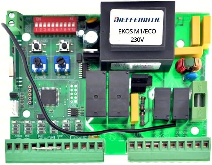
Figure 1: Dieffematic EKOS M1 230V Control Unit Circuit Board. An overhead view of the Dieffematic EKOS M1 230V control unit circuit board. It features a large transformer, a bank of red DIP switches labeled 1-10, two blue potentiometers for 'POWER' and 'SLOW P', push buttons for 'RADIO', and various green terminal blocks for connections. A fuse is visible on the right side, labeled 6/20. The board also includes several relays and integrated circuits.
Key components include:
- Transformer: Provides necessary power conversion.
- DIP Switches (1-10): Used for configuring various operational parameters.
- Potentiometers (POWER, SLOW P): Adjust motor power and slow-down speed.
- RADIO Buttons: For programming remote controls.
- Terminal Blocks: For connecting power, motor, safety devices, and control inputs (e.g., START, PED, STOP).
- Fuse (6/20): Overcurrent protection for the 230V input.
4. Setup and Installation
Warning: Ensure the main power supply is disconnected before proceeding with any installation steps.
4.1 Mounting the Control Unit
- Select a suitable, weather-protected location for the control unit enclosure.
- Mount the enclosure securely using appropriate fasteners.
4.2 Electrical Connections
Refer to the wiring diagram (not provided in this manual, consult product packaging or manufacturer's website) for specific connections. General connections include:
- Main Power Supply (230V): Connect to the designated terminals, ensuring proper grounding.
- Motor Connections: Connect the gate motor wires to the motor output terminals.
- Safety Devices: Connect photocells, safety edges, and other safety devices to their respective input terminals (e.g., STOP).
- Control Inputs: Connect push buttons, key switches, or other control devices to START, PED (pedestrian mode), and other relevant inputs.
- Accessories: Connect flashing lights, courtesy lights, or other accessories as required.
4.3 Initial Configuration (DIP Switches and Potentiometers)
The DIP switches (1-10) and potentiometers (POWER, SLOW P) allow for fine-tuning of the gate's operation. Consult the detailed configuration guide (not provided here) for specific settings based on your gate type and desired functionality.
- DIP Switches: Typically control features like automatic closing, pedestrian opening width, safety input types, etc.
- POWER Potentiometer: Adjusts the motor's force. Start with a lower setting and increase if necessary.
- SLOW P Potentiometer: Adjusts the speed during the slow-down phase of the gate's movement.
5. Operating Instructions
5.1 Basic Operation
- Opening/Closing: Press the designated button on your remote control or wired push button connected to the START input. A single press typically cycles the gate (open-stop-close-stop).
- Pedestrian Mode: If configured, pressing the button connected to the PED input will open the gate partially for pedestrian access.
- Stopping the Gate: During movement, pressing the START button again or activating a safety device (e.g., photocell) will stop the gate.
5.2 Remote Control Programming
To program a new remote control:
- Press and hold the 'RADIO' button on the control unit until an indicator light (if present) changes state.
- While the indicator is active, press the desired button on your remote control.
- The indicator light should confirm successful programming (e.g., flash, turn off).
- Test the remote control's functionality.
6. Maintenance
Regular maintenance ensures the longevity and reliable operation of your gate system.
- Annual Inspection: Have a qualified technician inspect the entire gate system, including the control unit, motor, and safety devices, at least once a year.
- Visual Check: Periodically inspect the control unit for any signs of damage, loose connections, or corrosion.
- Cleaning: Keep the control unit enclosure clean and free from dust, insects, and debris. Ensure ventilation openings are not blocked.
- Fuse Replacement: If the fuse blows (labeled 6/20), replace it only with a fuse of the identical type and rating to prevent damage to the unit.
7. Troubleshooting
This section addresses common issues. For complex problems, contact a qualified technician.
| Problem | Possible Cause | Solution |
|---|---|---|
| Gate does not move. | No power supply, blown fuse, faulty remote, safety device activated. | Check power connection, replace fuse (6/20), check remote battery, inspect safety devices (photocells, stop buttons). |
| Gate opens but does not close. | Safety device obstruction, automatic closing disabled, faulty limit switch. | Clear obstructions from safety device path, check DIP switch settings for automatic closing, inspect limit switches. |
| Gate moves erratically or stops mid-cycle. | Motor power setting too low, mechanical obstruction, faulty motor. | Adjust POWER potentiometer, check for mechanical obstructions, consult technician for motor inspection. |
8. Specifications
| Feature | Detail |
|---|---|
| Model | Dieffematic EKOS M1 230 |
| Input Voltage | 230V AC |
| Manufacturer Reference | 372685022286 |
| ASIN | B07ZQR7NPW |
| First Available Date | October 25, 2019 |
9. Warranty and Support
For warranty information, technical support, or service inquiries, please refer to the documentation provided with your purchase or contact Dieffematic directly through their official website or authorized distributors. Keep your proof of purchase for warranty claims.


