Dieffematic EKOS M1/ECO
Dieffematic EKOS M1/ECO 230V Control Board Instruction Manual
For Sliding Gate Automation Systems
1. Introduction
This manual provides detailed instructions for the installation, operation, and maintenance of the Dieffematic EKOS M1/ECO 230V control board. This board is designed for use with 230V sliding gate automation systems and is compatible with systems such as the BFT Mizar 6 Alpha.
Please read this manual carefully before proceeding with installation or operation to ensure proper functionality and safety.
2. Safety Instructions
Always observe the following safety precautions:
- Installation and maintenance must be performed by qualified personnel only.
- Disconnect power before performing any work on the control board or gate system.
- Ensure all electrical connections comply with local regulations and standards.
- Do not modify the control board or its components.
- Keep children and unauthorized persons away from the gate area during operation.
3. Product Overview and Components
The Dieffematic EKOS M1/ECO 230V control board is a central component for managing sliding gate operations. Below is an image illustrating the main features and connection points of the board.
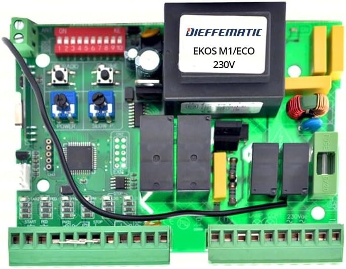
Figure 1: Dieffematic EKOS M1/ECO 230V Control Board. This image shows the green circuit board with various electronic components, including a large black transformer labeled "DIEFFEMATIC EKOS M1/ECO 230V", a red DIP switch block (labeled 1-10), blue potentiometers for "POWER" and "SLOW P", black relays, and green terminal blocks for wiring connections. A black wire is also visible.
Key components include:
- Transformer: Provides necessary voltage for the board's operation.
- DIP Switches (1-10): Used for configuring various operational parameters.
- Potentiometers (POWER, SLOW P): Adjustments for motor power and slow-down phase.
- Terminal Blocks: Connection points for power input, motor, safety devices, and control commands.
- Fuses: Overcurrent protection for the board.
4. Setup and Installation
4.1 Mounting the Control Board
- Choose a suitable, weather-protected enclosure for the control board.
- Mount the board securely within the enclosure using appropriate fasteners.
- Ensure adequate ventilation to prevent overheating.
4.2 Electrical Connections
Refer to the terminal block labels on the board for correct wiring. A general overview of connections:
- 230V Power Input: Connect the main 230V AC power supply to the designated terminals. Ensure proper grounding.
- Motor Connections: Connect the sliding gate motor wires (common, open, close) to the motor output terminals.
- Safety Devices: Connect photocells, safety edges, and other safety devices to their respective input terminals (e.g., STOP, FOTO).
- Command Inputs: Connect push buttons, key switches, or radio receivers to the command input terminals (e.g., START, PED).
- Accessories: Connect flashing lights, courtesy lights, or other accessories to the auxiliary output terminals.
4.3 DIP Switch Configuration
The red DIP switch block allows for customization of the board's behavior. Consult the specific wiring diagram provided with your gate system for detailed DIP switch settings. Common settings may include:
- Automatic closing time.
- Pre-flashing light activation.
- Pedestrian opening function.
- Photocell logic (normally open/closed).
Figure 2: Close-up of the DIP switches and potentiometers. This image highlights the red block of ten small switches labeled 1-10, and two blue potentiometers labeled "POWER" and "SLOW P", used for fine-tuning the gate's operation.
4.4 Potentiometer Adjustment
- POWER: Adjusts the motor's force. Turn clockwise to increase power, counter-clockwise to decrease.
- SLOW P: Adjusts the duration or speed of the slow-down phase at the end of the opening/closing cycle.
5. Operating Instructions
5.1 First Power-Up
After completing all electrical connections and configurations, apply power to the control board. Observe any indicator lights for proper functioning.
5.2 Learning Cycle (if applicable)
Some control boards require a learning cycle to determine the gate's travel limits. Follow the specific procedure outlined in your gate motor's manual or the board's detailed instructions for this process.
5.3 Normal Operation
Activate the gate using your chosen command device (e.g., remote control, push button). The gate should open or close smoothly according to the configured settings.
6. Maintenance
Regular maintenance ensures the longevity and reliable operation of your control board and gate system.
- Visual Inspection: Periodically inspect the board for any signs of damage, corrosion, or loose connections.
- Cleaning: Keep the board free from dust and debris. Use a soft, dry brush or compressed air for cleaning. Do not use liquids.
- Fuse Check: If the board loses power, check the fuses (e.g., FUSE 6/20) and replace them with fuses of the same rating if blown.
- Terminal Tightness: Ensure all terminal connections remain tight.
7. Troubleshooting
This section provides solutions to common issues. For complex problems, contact qualified technical support.
| Problem | Possible Cause | Solution |
|---|---|---|
| Gate does not respond to commands. | No power, blown fuse, faulty remote, safety device activated. | Check power supply, replace fuse, check remote battery, inspect safety devices (photocells). |
| Gate opens but does not close. | Photocells obstructed or misaligned, closing limit switch issue. | Clear photocell path, clean lenses, realign photocells, check closing limit switch. |
| Gate stops unexpectedly. | Obstruction detected, motor overheating, faulty sensor. | Remove obstruction, allow motor to cool, check sensor connections. |
8. Technical Specifications
- Model: Dieffematic EKOS M1/ECO
- Input Voltage: 230V AC
- Compatibility: Sliding gate automation systems, compatible with BFT Mizar 6 Alpha
- Manufacturer: Dieffematic
- ASIN: B07ZKM5YW4
- First Available Date: 14 October 2019
9. Warranty Information
This product is covered by a standard manufacturer's warranty. For specific warranty terms and conditions, please refer to the documentation provided at the time of purchase or contact Dieffematic customer support. The warranty typically covers defects in materials and workmanship under normal use.
10. Customer Support
For technical assistance, spare parts, or further inquiries, please contact your authorized Dieffematic dealer or visit the official Dieffematic website. When contacting support, please have your product model (EKOS M1/ECO) and ASIN (B07ZKM5YW4) ready.
Manufacturer: Dieffematic
Seller: DIEFFEMATIC (via Amazon.it)
Related Documents - EKOS M1/ECO
 |
Dieffematic RX Multifrequency 433/868 MHz Manual This manual provides instructions and specifications for the Dieffematic RX Multifrequency receiver, covering its features, programming, and compatibility with various remote control brands. |
 |
Allmatic CONTROL UNIT BIOS2 ECO Installation Manual Installation manual for the Allmatic CONTROL UNIT BIOS2 ECO, a programmable control board for wing gates. Details setup, connections, configuration, and advanced settings for gate automation systems. |
 |
Calimet M1 Sliding Gate Operator Installation and Owner Manual This manual provides comprehensive instructions for the installation, operation, and maintenance of the Calimet M1 Sliding Gate Operator. It covers safety precautions, electrical requirements, installation procedures, accessory wiring, and troubleshooting. |
 |
StellarMate X User Manual: Astrophotography Controller Guide Comprehensive user manual for the StellarMate X, a powerful astrophotography controller by Ikarus Technologies. Learn about setup, software features like Ekos and INDI, equipment connection, and troubleshooting for advanced astronomical imaging. |
 |
EQStarPro User Guide This user guide provides comprehensive instructions for setting up and operating the EQStarPro, an equatorial mount control system. Learn how to connect and control your telescope via PC, mobile devices, or standalone joystick for astrophotography and visual astronomy. |