1. Introduction
This manual provides essential information for the safe and effective installation, operation, and maintenance of the ALLEN BRADLEY 150-C108NBD Soft Starter SMC-3. This device is designed for controlling the starting and stopping of AC motors, reducing mechanical stress on the motor and connected equipment, and minimizing current surges during startup.
The 150-C108NBD is a robust industrial component, featuring a 10A AMP current rating, suitable for 75HP motors, and operating within a 200-480V-AC voltage range. Please read this manual thoroughly before attempting any installation or operation.
2. Safety Information
WARNING: Risk of electric shock. Only qualified personnel should install, operate, or service this equipment. Disconnect all power before working on the device.
Observe all local and national electrical codes. Failure to follow these instructions can result in serious injury or death.
- Ensure proper grounding of the equipment.
- Do not operate the device with damaged components.
- Always verify voltage and current ratings before connection.
- A "CAUTION" label is present on the device regarding delta connection motors. This label states: "CAUTION: inside the delta connection motors only. Remove after installation. Read user's manual." This indicates a temporary component or instruction specific to certain wiring configurations that must be addressed during installation.
3. Product Overview
The ALLEN BRADLEY 150-C108NBD Soft Starter SMC-3 is designed for robust industrial applications. It features a compact design with clearly labeled terminals for easy connection.
3.1. Components and Features
- Power Terminals: T1/2, T2/4, T3/6 for motor connections and T4/8, T5/10, T6/12 for line connections.
- Control Terminals: For auxiliary control signals.
- Status Indicators: LEDs for operational status.
- Cooling Vents: Designed for efficient heat dissipation.
- Mounting Points: For secure installation within an enclosure.
3.2. Product Views

Figure 3.2.1: Front view of the soft starter, showing the main body and terminal blocks. The "AB SMC-3" logo is visible on the front panel.

Figure 3.2.2: Top-down view, highlighting the terminal connections (T1/2, T2/4, T3/6, T4/8, T5/10, T6/12) and the caution label regarding delta connection motors.
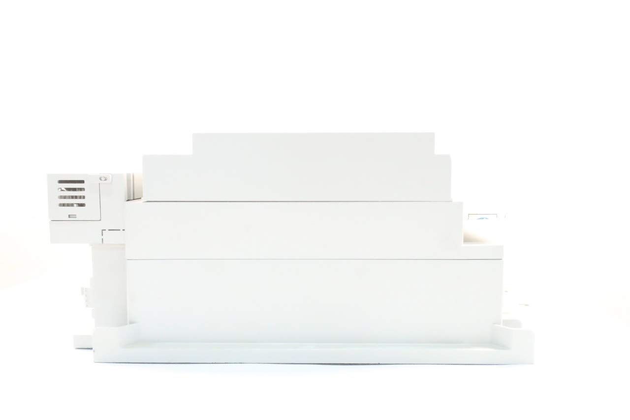
Figure 3.2.3: Side profile of the soft starter, showing its compact form factor.

Figure 3.2.4: Rear view, showing cooling fins and mounting points.

Figure 3.2.5: Side view displaying the product label with model number and electrical specifications.
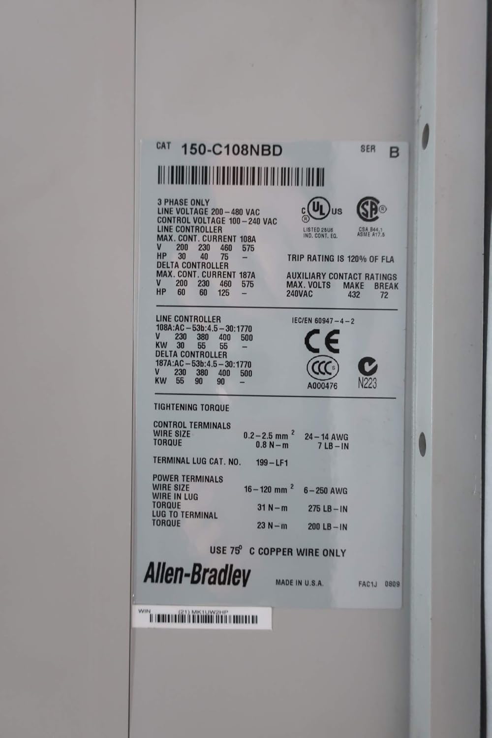
Figure 3.2.6: Detailed view of the product label, showing CAT 150-C108NBD, UL, CSA, CE markings, and detailed electrical ratings for line and delta controller configurations. Also visible is a barcode with the number 21MK1UW2HP and the model number 150-C108NBD B.

Figure 3.2.7: Close-up of a barcode label with number 40891-454-11 and FRN 2.08. The barcode value is 61100C13.

Figure 3.2.8: Close-up of a shipping or inventory label, confirming the product as "ALLEN BRADLEY 150-C108NBD SMC-3 10A AMP 75HP 200-480V-AC SOFT STARTER". A barcode with number 0723946 is visible.
4. Technical Specifications
| Attribute | Value |
|---|---|
| Model Number | 150-C108NBD |
| Brand | Allen-Bradley |
| Current Rating | 10 Amps |
| Power Rating | 75 HP |
| Voltage Range | 200 - 480 V-AC |
| Product Dimensions (L x W x H) | 20.5 x 11 x 10.75 inches |
| Item Weight | 32.9 Pounds |
| Manufacturer | ALLEN BRADLEY |
| Date First Available | October 14, 2019 |
Note: For detailed wiring diagrams and specific application guidelines, refer to the official Allen-Bradley documentation for the SMC-3 series.
5. Setup and Installation
Installation of the 150-C108NBD Soft Starter should only be performed by qualified electricians in accordance with all applicable electrical codes and standards.
5.1. Pre-Installation Checklist
- Verify that the supply voltage matches the soft starter's rating (200-480V-AC).
- Ensure adequate space for ventilation around the unit.
- Confirm that the motor's current and HP ratings are compatible with the soft starter (10A, 75HP).
- Have all necessary tools and personal protective equipment (PPE) available.
5.2. Mounting
Mount the soft starter vertically on a flat, stable surface within an appropriate electrical enclosure. Ensure proper clearance for cooling and access to terminals.
5.3. Wiring
Connect the line voltage to the input terminals (L1, L2, L3) and the motor to the output terminals (T1, T2, T3). Refer to the product label (Figure 3.2.6) for specific terminal designations and tightening torques. Ensure all connections are secure and properly insulated.
Important Note on Delta Connections:
As indicated by the caution label on the device (Figure 3.2.2), if using a delta connection for motors, ensure that any internal components or instructions related to this configuration are followed precisely and removed if specified after installation. Consult the full SMC-3 series manual for detailed delta wiring diagrams.
5.4. Control Wiring
Connect control signals (e.g., start/stop, fault reset) to the designated control terminals. Refer to the detailed wiring diagrams provided in the complete product manual for specific control schemes.
6. Operating Instructions
Once installed and wired correctly, the soft starter is ready for operation. The SMC-3 series typically offers various starting and stopping profiles. For detailed programming and parameter settings, refer to the comprehensive SMC-3 user manual.
6.1. Initial Power-Up
- Before applying power, double-check all wiring connections.
- Apply main power to the soft starter. Observe any status indicators for normal operation.
- If any fault indicators illuminate, immediately disconnect power and refer to the troubleshooting section.
6.2. Starting the Motor
Initiate the motor start sequence via the connected control system (e.g., pressing a start button). The soft starter will gradually increase the voltage to the motor, providing a smooth, controlled acceleration.
6.3. Stopping the Motor
Initiate the motor stop sequence. The soft starter will gradually decrease the voltage, providing a controlled deceleration, reducing mechanical shock.
7. Maintenance
Regular maintenance ensures the longevity and reliable operation of your soft starter. Always disconnect power before performing any maintenance.
- Periodic Inspection: Visually inspect the unit for any signs of damage, loose connections, or overheating (discoloration).
- Cleaning: Keep the unit clean and free of dust and debris, especially around cooling vents. Use compressed air if necessary.
- Terminal Tightness: Periodically check and re-tighten all power and control terminal connections to ensure good electrical contact. Refer to the torque specifications on the product label (Figure 3.2.6).
- Environmental Conditions: Ensure the operating environment remains within specified temperature and humidity ranges.
8. Troubleshooting
This section provides general troubleshooting steps. For detailed fault codes and advanced diagnostics, consult the complete SMC-3 series manual.
| Problem | Possible Cause | Solution |
|---|---|---|
| Soft Starter does not power on. | No input power; Blown fuse/breaker; Incorrect wiring. | Check main power supply; Inspect fuses/breakers; Verify wiring connections. |
| Motor does not start. | Control signal issue; Motor overload; Incorrect parameters. | Check control wiring; Verify motor load; Consult manual for parameter settings. |
| Soft Starter trips frequently. | Overcurrent; Overheating; Ground fault; Motor issue. | Check motor current; Ensure adequate ventilation; Inspect motor and wiring for faults. |
| Abnormal noise or vibration. | Loose connections; Internal component failure; Motor issue. | Tighten all connections; If problem persists, contact qualified service personnel. |
9. Warranty and Support
For warranty information and technical support regarding your ALLEN BRADLEY 150-C108NBD Soft Starter SMC-3, please refer to the official Allen-Bradley website or contact your authorized distributor. Ensure you have the model number (150-C108NBD) and serial number (if applicable) ready when seeking support.
For additional resources and detailed documentation, visit the Allen-Bradley official website.


