1. Product Overview
The Flo Dynamics PSI Cool Coolant Service Machine (P/N 98012) is designed for efficient and comprehensive vehicle coolant system maintenance. This unit operates solely on compressed air, eliminating the need for electrical power. It facilitates various services including coolant flushing, air pocket removal, coolant draining for component replacement, and vacuum/fill procedures. Its design emphasizes ease of use with clear service hoses for fluid monitoring and dual sight tubes for quick tank level identification.
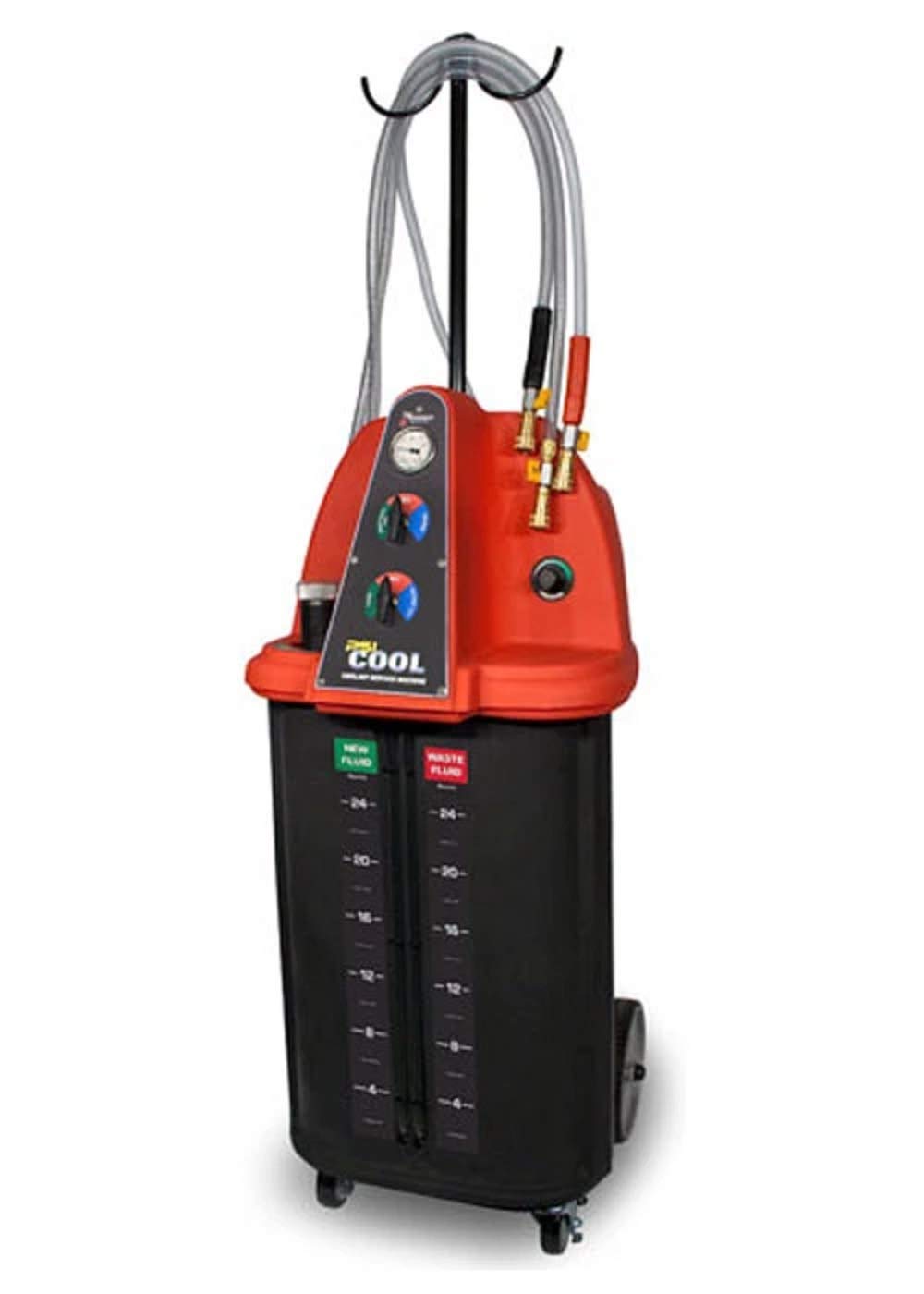
Figure 1: Front view of the Flo Dynamics PSI Cool Coolant Service Machine. The machine features a pressure gauge at the top and two rotary valves for controlling fluid flow and vacuum operations. The "PSI Cool" logo is prominently displayed at the bottom.
2. Safety Information
Always prioritize safety when operating the Flo Dynamics PSI Cool Coolant Service Machine. Failure to follow safety precautions can result in injury or equipment damage.
- Personal Protective Equipment (PPE): Always wear appropriate PPE, including safety glasses, gloves, and protective clothing, when handling coolants.
- Ventilation: Ensure adequate ventilation in the work area to prevent inhalation of coolant vapors.
- Compressed Air: Use only clean, dry compressed air at the specified pressure (115 PSI). Do not exceed the maximum recommended pressure.
- Coolant Handling: Coolants are toxic. Avoid skin contact and ingestion. Dispose of used coolant according to local environmental regulations.
- Machine Stability: Ensure the machine is placed on a stable, level surface before operation to prevent tipping.
- Hose Connections: Verify all hoses and connections are secure and free from leaks before applying pressure or vacuum.
- Emergency Procedures: Know the location of emergency shut-off valves for compressed air and have spill containment materials readily available.
3. Setup and Initial Preparation
Before operating the PSI Coolant Service Machine, perform the following setup steps:
- Unpacking: Carefully remove the machine and all accessories from its packaging. Inspect for any shipping damage.
- Placement: Position the machine on a flat, stable surface in a well-ventilated area.
- Connect Air Supply: Connect a clean, dry compressed air line to the machine's air inlet. Ensure the air pressure is regulated to 115 PSI.
- Accessory Identification: Familiarize yourself with the included hoses, adapters, and other accessories.

Figure 2: Various accessories included with the coolant service machine. This image displays different types of clamps, hoses, adapters, and protective gloves, essential for connecting the machine to a vehicle's cooling system.
4. Operating Instructions
The PSI Coolant Service Machine offers several functions for comprehensive coolant system maintenance. Always refer to the vehicle manufacturer's service manual for specific coolant types and procedures.
4.1. General Operation Principles
- The machine uses compressed air to create a vacuum or pressure for fluid transfer.
- Clear service hoses allow visual monitoring of fluid flow.
- Dual sight tubes indicate the levels in the new fluid and waste fluid tanks.
- The top rotary valve controls waste fluid drainage and vacuum for the system.
- The bottom rotary valve controls new fluid filling and vacuum testing.
4.2. Performing a Vacuum and Fill Service
This procedure removes air from the cooling system and refills it with new coolant without introducing air pockets.
- Prepare Vehicle: Ensure the engine is cool. Drain existing coolant if necessary (refer to Section 4.3).
- Connect Hoses: Select appropriate adapters and connect the machine's service hoses to the vehicle's cooling system (e.g., radiator hose, overflow tank). Ensure connections are secure.
- Apply Vacuum:
- Turn the top rotary valve to the "VACUUM" position.
- Open the air supply to the machine.
- Observe the pressure gauge. A vacuum will be drawn on the cooling system. Allow the vacuum to stabilize and hold for several minutes to confirm no leaks.
- If vacuum does not hold, check all connections for leaks and repair as needed.
- Fill with New Coolant:
- Ensure the new fluid tank is filled with the correct type and amount of coolant (7 Gallons capacity).
- Turn the bottom rotary valve to the "FILL" position.
- The vacuum in the cooling system will draw the new coolant from the machine's tank into the vehicle's system.
- Monitor the clear hoses and sight tubes until the system is full.
- Close the air supply and disconnect hoses.
- Final Checks: Start the engine, check for leaks, and verify coolant levels.

Figure 3: Example of service hose connection to a vehicle's cooling system. This image shows quick-connect fittings attached to a radiator hose, illustrating how the machine interfaces with the vehicle for fluid exchange.
4.3. Draining Coolant for Component Change
This function allows for quick and clean removal of coolant from the system.
- Prepare Vehicle: Ensure the engine is cool.
- Connect Hoses: Connect the machine's waste fluid hose to a suitable point in the vehicle's cooling system.
- Drain Coolant:
- Ensure the waste fluid tank has sufficient capacity (8 Gallons capacity).
- Turn the top rotary valve to the "DRAIN WASTE TANK" position.
- Open the air supply to the machine. The machine will draw coolant from the vehicle into its waste tank.
- Monitor the clear hoses and sight tubes until the system is drained.
- Close the air supply and disconnect hoses.
- Dispose of Waste: Properly dispose of the collected waste coolant according to environmental regulations.

Figure 4: Another view of service hose connections within an engine bay. This image highlights the flexibility of hose routing and adapter usage for various vehicle configurations during coolant service.
4.4. Full Flush Service
A full flush service involves circulating a cleaning agent or fresh water through the system before refilling with new coolant.
- Initial Drain: Perform a coolant drain as described in Section 4.3.
- Introduce Flushing Agent: Fill the new fluid tank with a suitable flushing agent or clean water. Connect the fill hose to the vehicle.
- Circulate: Use the machine to circulate the flushing agent through the system. This may involve running the engine for a short period (consult flushing agent instructions).
- Drain Flushing Agent: Drain the flushing agent into the waste tank. Repeat with clean water if necessary until the drained fluid is clear.
- Vacuum and Fill: Perform a vacuum and fill service with new coolant as described in Section 4.2.

Figure 5: Close-up of a coolant hose connection point on an engine. This image demonstrates the secure attachment of the service hose to a vehicle's coolant line, ensuring a leak-free operation during fluid transfer.
5. Maintenance
Regular maintenance ensures the longevity and reliable operation of your PSI Coolant Service Machine.
- Cleanliness: Keep the machine clean. Wipe down exterior surfaces after each use.
- Hose Inspection: Regularly inspect all hoses for cracks, kinks, or damage. Replace damaged hoses immediately.
- Adapter Inspection: Check adapters for wear or damage. Ensure O-rings are intact and sealing properly.
- Tank Cleaning: Periodically clean the new fluid and waste fluid tanks to prevent contamination.
- Air Supply: Ensure your compressed air supply is filtered and dry to prevent moisture and contaminants from entering the machine.
- Storage: Store the machine in a clean, dry environment when not in use.
6. Troubleshooting
This section provides solutions to common operational issues.
| Problem | Possible Cause | Solution |
|---|---|---|
| Machine does not draw vacuum. |
|
|
| Coolant does not fill into vehicle. |
|
|
| Slow fluid transfer. |
|
|
7. Technical Specifications
- Model: P/N 98012
- Power Source: 115 P.S.I. Compressed Air
- Dimensions (H x W x D): 52 inches x 23 inches x 27 inches
- New Fluid Tank Capacity: 7 Gallons
- Waste Fluid Tank Capacity: 8 Gallons
- Weight: 160 lbs.
- Manufacturer: Flo Dynamics
8. Warranty and Support
Specific warranty details for the Flo Dynamics PSI Cool Coolant Service Machine (P/N 98012) are not provided in this document. For warranty information, technical support, or to order replacement parts, please contact Flo Dynamics directly or refer to the documentation included with your purchase.
Always use genuine Flo Dynamics replacement parts to ensure proper function and maintain warranty validity.


