
1. Introduction
The DIATONE Mamba F405 Mini F4 Flight Controller is a high-performance control unit designed for FPV racing drones and quadcopters. It integrates essential components such as an F405 MCU, MPU6500 gyroscope, Betaflight OSD, and multiple BEC outputs, providing a robust and versatile platform for your aerial vehicle. This manual provides detailed instructions for installation, configuration, operation, and maintenance to ensure optimal performance and longevity of your flight controller.

Figure 1: Top view of the DIATONE Mamba F405 Mini F4 Flight Controller, showing the main MCU and gyroscope.
2. Features
The Mamba F405 Mini F4 Flight Controller is equipped with a range of features to enhance your FPV experience:
- MCU: 168M STM32F405 for high processing power.
- GYRO: MPU6500 for precise flight stabilization.
- OSD: Integrated Betaflight On-Screen Display for real-time flight data.
- Blackbox: 16M Flash Memory for flight logging and tuning analysis.
- Barometer: SPL06 for accurate altitude holding.
- UARTs: 6 sets for connecting various peripherals (GPS, VTX, Receiver, etc.).
- I2C: Yes, for external compass or other I2C devices.
- F.Port: Yes, for FrSky F.Port receivers.
- Buzzer Pad: Yes, for audible alerts.
- CURR Pad: Yes, for current sensor input.
- ESC Signal: 6 sets, supporting Dshot300/600/1200 protocols.
- ESC Telemetry: Yes, for monitoring ESC data.
- Power LED: Yes, for power status indication.
- LED Controller: BF LED for programmable LED strips.
- AIR UNIT Port: Yes, for direct connection to DJI Air Unit.
- VTX Switch: Yes, for controlling video transmitter power.
- Receiver Protection: Yes.
- TVS Protection: Yes, for transient voltage suppression.
- BEC: Multiple outputs: 3.3V 0.5A, 5V 2.5A, and 9V 2A.
- Input: 3~6S Lipo (12.6~25.2V) for wide power compatibility.
- Mounting Size: 20mm x 20mm, M2/M3 holes.
3. Specifications
Detailed technical specifications for the DIATONE Mamba F405 Mini F4 Flight Controller:
| Component | Specification |
|---|---|
| MCU | STM32F405 (168MHz) |
| Gyroscope | MPU6500 |
| OSD | Yes (Betaflight OSD) |
| Blackbox | 16M Flash Memory |
| Barometer | SPL06 |
| UARTs | 6 Sets |
| I2C | Yes |
| F.Port | Yes |
| Buzzer Pad | Yes |
| CURR Pad | Yes |
| ESC Signal | 6 Sets (Dshot300/600/1200) |
| ESC Telemetry | Yes |
| Power LED | Yes |
| LED Controller | BF LED |
| AIR UNIT Port | Yes |
| VTX Switch | Yes |
| Receiver Protection | Yes |
| TVS Protection | Yes |
| BEC Output 1 | 3.3V 0.5A |
| BEC Output 2 | 5V 2.5A |
| BEC Output 3 | 9V 2A |
| Input Voltage | 3~6S Lipo (12.6~25.2V) |
| Mounting Size | 20mm x 20mm, M2/M3 |
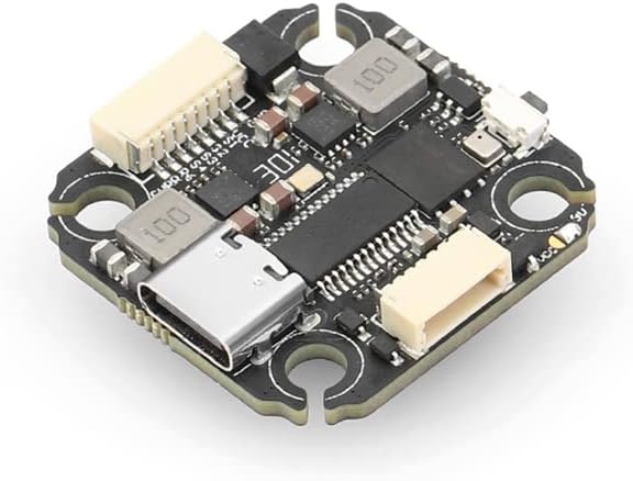
Figure 2: Bottom view of the flight controller, highlighting the USB-C port and various solder pads.
4. Setup
Proper setup is crucial for the stable operation of your FPV drone. Follow these steps carefully:
4.1. Mounting
- Ensure your drone frame has a 20x20mm mounting pattern.
- Use appropriate M2 or M3 standoffs and screws to securely mount the flight controller. Avoid overtightening to prevent damage to the PCB.
- Orient the flight controller correctly. The arrow on the board typically indicates the forward direction of the drone. Adjust in Betaflight if necessary.
4.2. Wiring
Connect your peripherals to the flight controller according to the wiring diagram provided with your drone frame or ESC. Common connections include:
- ESCs: Connect the ESC signal wires to the corresponding motor outputs (M1-M6) on the flight controller. Connect ESC telemetry if supported.
- Receiver: Connect your receiver (e.g., SBUS, CRSF, F.Port, PPM) to the appropriate UART pads. Ensure correct voltage supply (5V or 3.3V).
- VTX (Video Transmitter): Connect the VTX video input to the VTX pad and power (9V or 5V BEC). Utilize the VTX switch feature if desired.
- Camera: Connect the FPV camera video output to the CAM pad and power (5V BEC).
- GPS (Optional): Connect GPS module to a dedicated UART.
- Buzzer (Optional): Connect to the buzzer pads.
- LEDs (Optional): Connect programmable LED strips to the LED pad.

Figure 3: Side view of the flight controller showing various connectors and solder pads for peripheral connections.
4.3. Firmware Flashing (Betaflight)
- Download and install the latest Betaflight Configurator software on your computer.
- Connect the flight controller to your computer via a USB-C cable.
- In Betaflight Configurator, navigate to the 'Firmware Flasher' tab.
- Select the correct target for your flight controller (e.g.,
MAMBAF405MINI). - Choose the latest stable firmware version.
- Click 'Load Firmware [Online]' and then 'Flash Firmware'.
- After flashing, click 'Connect' to access the flight controller settings.
4.4. Configuration
Configure the flight controller settings in Betaflight Configurator:
- Ports Tab: Enable serial RX for your receiver's UART, and configure other peripherals (VTX, GPS) on their respective UARTs.
- Configuration Tab: Set DShot protocol, accelerometer, barometer, and OSD features. Configure motor direction and layout.
- Receiver Tab: Verify receiver input and channel mapping.
- Modes Tab: Set up arming, flight modes (Angle, Acro, Horizon), and other auxiliary functions.
- PID Tuning: Adjust PID values for optimal flight performance. Start with default settings and fine-tune as needed.
- Save and Reboot: Always save your changes and allow the flight controller to reboot.
5. Operating
Once the flight controller is set up and configured, you can proceed with operating your FPV drone.
5.1. Pre-Flight Checks
- Ensure all connections are secure and free from shorts.
- Verify propeller direction and tightness.
- Check battery voltage and charge level.
- Confirm radio control link and arming switch functionality.
5.2. Powering On
Connect the LiPo battery to your drone. The flight controller will power on, and you should hear a series of beeps from the ESCs indicating initialization. The LED on the flight controller will show its status (e.g., solid for armed, blinking for disarmed).
5.3. Arming and Disarming
- Arming: Move the designated arming switch on your radio to the 'armed' position. The motors will typically spin slowly, indicating they are ready for flight. Ensure you are in a safe area before arming.
- Disarming: Move the arming switch back to the 'disarmed' position. The motors will stop. Always disarm immediately after landing or in case of an emergency.
5.4. Flight Modes
Utilize the configured flight modes (e.g., Angle, Acro, Horizon) via your radio switches to control the drone's behavior. Refer to Betaflight documentation for detailed explanations of each mode.
6. Maintenance
Regular maintenance helps ensure the reliability and longevity of your flight controller and drone.
- Visual Inspection: Periodically inspect the flight controller for any signs of physical damage, loose connections, or burnt components.
- Cleaning: Gently clean the board with a soft brush or compressed air to remove dust, dirt, or debris. Avoid using liquids directly on the board.
- Firmware Updates: Keep your Betaflight firmware updated to the latest stable version to benefit from bug fixes and new features. Always back up your configuration before updating.
- Solder Joint Checks: Ensure all solder joints are solid and free from cracks or cold joints. Re-solder if necessary.
- Environmental Protection: If flying in damp or dusty conditions, consider conformal coating for added protection.
7. Troubleshooting
This section addresses common issues you might encounter with your Mamba F405 Mini F4 Flight Controller.
7.1. No Power to Flight Controller
- Check Battery Connection: Ensure the LiPo battery is properly connected and charged.
- Check Main Power Leads: Inspect the main power wires from the battery to the ESC/PDB and then to the flight controller for continuity and secure soldering.
- Inspect for Shorts: Look for any solder bridges or exposed wires that could cause a short circuit.
7.2. No ESC Communication / Motors Not Spinning
- Check Signal Wires: Ensure ESC signal wires are correctly connected to the flight controller's motor outputs.
- ESC Protocol: Verify that the ESC protocol (e.g., DShot600) is correctly configured in Betaflight and matches your ESCs.
- ESC Firmware: Ensure ESCs have compatible firmware (e.g., BLHeli_S, BLHeli_32).
- Motor Direction: Check motor direction in Betaflight's motor tab.
7.3. Receiver Not Detected
- Wiring: Confirm receiver signal and power wires are correctly connected to the designated UART on the flight controller.
- UART Configuration: In Betaflight's 'Ports' tab, ensure 'Serial RX' is enabled for the correct UART.
- Receiver Protocol: Verify the receiver protocol (e.g., SBUS, CRSF) is correctly selected in Betaflight's 'Configuration' tab.
- Binding: Ensure your receiver is properly bound to your radio transmitter.
7.4. Flight Instability / Drifting
- Calibration: Calibrate the accelerometer in Betaflight on a level surface.
- Mounting: Ensure the flight controller is securely mounted and isolated from vibrations.
- PID Tuning: Default PID values may not be optimal for all setups. Adjust PID values gradually.
- Propellers: Check for damaged or unbalanced propellers.
8. Warranty and Support
DIATONE products are manufactured to high standards. For warranty information, please refer to the specific terms and conditions provided at the time of purchase or visit the official DIATONE website. If you encounter issues that cannot be resolved using this manual, please contact DIATONE customer support or your authorized dealer for assistance. Provide your product model number (Mamba F405 Mini) and a detailed description of the problem when seeking support.