
1. Introduction
This manual provides essential information for the safe and efficient installation, operation, and maintenance of your VEVOR 2 Spool Hydraulic Directional Control Valve. Please read this manual thoroughly before using the product to ensure proper function and to prevent damage or injury. Keep this manual for future reference.
Safety Information
- Always wear appropriate personal protective equipment (PPE) such as safety glasses and gloves when working with hydraulic systems.
- Ensure the hydraulic system is depressurized before performing any installation, maintenance, or troubleshooting.
- High-pressure hydraulic fluid can cause serious injury. Never use bare hands to check for leaks.
- Ensure all connections are secure and properly sealed to prevent leaks.
- Only qualified personnel should perform installation and maintenance procedures.
2. Product Overview
The VEVOR 2 Spool Hydraulic Directional Control Valve is designed for precise control of double-acting hydraulic cylinders in various applications. Its robust construction and high-performance capabilities make it suitable for demanding industrial and agricultural environments.
Key Features
- Double Acting: Specifically engineered for operating double-acting hydraulic cylinders, allowing for controlled extension and retraction.
- Durable Construction: Manufactured from cast iron for enhanced durability and long-term reliability in harsh conditions. Features 2 spools and 1/2 BSPP O-ring inlet/outlet ports.
- High Performance: Capable of handling pressures up to 3600 PSI and a maximum flow rate of 11 GPM, ensuring efficient hydraulic power delivery.
- Spring Return: Each spool valve is equipped with a spring return mechanism, automatically returning the lever to the neutral position when released.
- Wide Application: Ideal for use in small tractors, tractor loaders, log splitters, and other hydraulic machinery requiring precise directional control.

Image: Close-up view highlighting the solid cast iron construction and protected ports of the hydraulic valve.

Image: The hydraulic valve with its control levers, illustrating its high-performance design and typical installation in machinery.
3. Setup and Installation
3.1 Pre-Installation Checks
- Verify that the valve specifications (pressure, flow, port size) match your hydraulic system requirements.
- Inspect the valve for any visible damage from shipping.
- Ensure all necessary fittings, hoses, and mounting hardware are available.
3.2 Mounting the Valve
- Select a secure and accessible location for mounting the valve, away from excessive heat, vibration, and potential impact.
- Use appropriate bolts and washers to firmly attach the valve to a stable surface. Ensure the mounting surface can support the weight of the valve and the forces exerted during operation.
3.3 Connecting Hydraulic Lines
The valve features 1/2 BSPP O-ring inlet/outlet ports. Ensure proper thread type and size for all connections.
- Pressure Line (P): Connect the pressure line from your hydraulic pump to the 'P' port on the valve.
- Tank Line (T): Connect the return line to the hydraulic reservoir (tank) to the 'T' port.
- Work Ports (A & B): Connect the 'A' and 'B' ports for each spool to the respective ports on your double-acting hydraulic cylinders. For a 2-spool valve, you will have A1/B1 and A2/B2 ports.
- Use thread sealant or PTFE tape on all threaded connections to prevent leaks, ensuring not to block the fluid path.
- Tighten all fittings to the manufacturer's recommended torque specifications.

Image: Detailed view of the valve's internal check and relief valve components, crucial for system protection.
3.4 Initial System Checks
- After installation, slowly start the hydraulic pump and check for any leaks around the valve and connections.
- Operate the cylinders slowly through their full range of motion to bleed air from the system.
- Monitor system pressure and fluid levels.
4. Operating Instructions
The VEVOR 2 Spool Hydraulic Directional Control Valve provides intuitive control over your hydraulic cylinders. Each lever controls one spool, corresponding to a pair of work ports (A and B).
4.1 Lever Positions
- Neutral Position: When the lever is in the center, the spool is in the neutral position. In this state, fluid flow to the work ports is blocked, and the cylinder remains stationary. The spring return mechanism ensures the lever returns to this position when released.
- Extend Position: Pushing the lever forward (or in one direction) directs hydraulic fluid to one work port (e.g., 'A'), causing the cylinder to extend.
- Retract Position: Pulling the lever backward (or in the opposite direction) directs hydraulic fluid to the other work port (e.g., 'B'), causing the cylinder to retract.

Image: The hydraulic valve demonstrating the spring return function of its control levers, ensuring they snap back to neutral.
4.2 General Operation Guidelines
- Operate levers smoothly and avoid abrupt movements to prevent shock loads on the hydraulic system.
- Do not exceed the maximum operating pressure or flow rate specified for the valve.
- Regularly check for unusual noises, vibrations, or changes in performance during operation.

Image: Detailed view of the control levers, highlighting the design for multiple control methods and ease of use.
5. Maintenance
Proper maintenance ensures the longevity and reliable performance of your hydraulic control valve.
5.1 Regular Inspections
- Daily/Weekly: Check for any external leaks, loose connections, or visible damage to the valve body or levers.
- Monthly/Quarterly: Inspect hydraulic hoses and fittings for wear, cracks, or corrosion. Ensure mounting bolts are tight.
5.2 Hydraulic Fluid
- Ensure the hydraulic fluid level in the reservoir is adequate and within the recommended range.
- Check the condition of the hydraulic fluid. Replace fluid and filters according to your hydraulic system manufacturer's recommendations or if the fluid appears contaminated.
- Using clean, appropriate hydraulic fluid is critical for valve performance and system health.
5.3 Cleaning
- Keep the exterior of the valve clean and free from dirt, debris, and excessive oil buildup.
- Avoid using harsh chemicals that could damage seals or paint.
6. Troubleshooting
Before attempting any repairs, ensure the hydraulic system is depressurized and secured.
| Problem | Possible Cause | Solution |
|---|---|---|
| Cylinder does not move or moves slowly | Low hydraulic fluid level Clogged filter Pump malfunction Relief valve setting too low Air in the system | Check and refill hydraulic fluid Replace hydraulic filter Inspect or repair pump Adjust relief valve to correct pressure Bleed air from the system |
| Fluid leaks from valve or connections | Loose fittings Damaged O-rings or seals Incorrect thread type (e.g., NPT vs. BSPP) | Tighten fittings Replace damaged O-rings or seals Ensure correct fittings and adapters are used for BSPP ports |
| Lever does not return to neutral | Damaged or worn return spring Contamination in spool bore | Inspect and replace spring Disassemble and clean spool (professional service recommended) |
| Overheating hydraulic fluid | Insufficient fluid level Clogged cooler Continuous operation at high pressure | Check and refill fluid Clean or replace cooler Allow system to cool periodically |
7. Specifications
Detailed technical specifications for the VEVOR 2 Spool Hydraulic Directional Control Valve.
| Feature | Detail |
|---|---|
| Brand | VEVOR |
| Model Number | Hydraulic Valve 2 Spool 11gpm |
| Material | Cast Iron |
| Item Dimensions (L x W x H) | 9.05 x 7.48 x 3.94 inches |
| Item Weight | 9.8 pounds |
| Number of Spools | 2 |
| Maximum Operating Pressure | 3600 PSI |
| Maximum Flow Rate | 11 GPM |
| Inlet/Outlet Connection Size | 0.38 inches (1/2 BSPP O-ring) |
| Thread Type | BSPP (British Standard Parallel Pipe Thread) |
| Valve Type | Directional Control Valve with Relief Valve |
| Included Components | 1 x 2 Spool Hydraulic Directional Control Valve 11 GPM Double Acting Cylinder Spool |
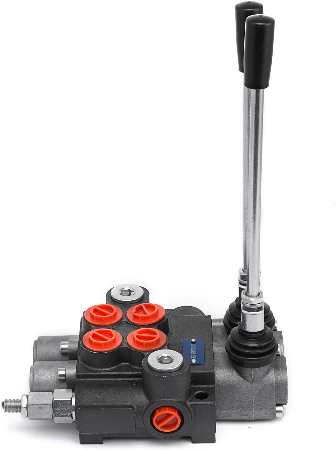
Image: Dimensional drawing of the hydraulic valve, indicating overall length, width, and height.
8. Warranty and Support
8.1 Warranty Information
VEVOR products are manufactured to high-quality standards and are covered by a manufacturer's warranty. For specific warranty terms and conditions, please refer to the warranty card included with your product or visit the official VEVOR website.
8.2 Customer Support
If you have any questions, require technical assistance, or need to report an issue with your VEVOR 2 Spool Hydraulic Directional Control Valve, please contact VEVOR customer support. Contact information can typically be found on the VEVOR official website or on the product packaging.


