
1. Introduction
The AITRIP DS1302 Clock Module is a low-power, full binary-coded decimal (BCD) clock/calendar plus 31 bytes of static RAM. It is designed to provide real-time clock functions to microcontrollers such as Arduino, AVR, and ARM platforms. This module communicates with a microcontroller via a simple 3-wire serial interface, making it easy to integrate into various electronic projects requiring accurate timekeeping.
2. Features
- Integrates a real-time clock/calendar and 31 bytes of static RAM.
- Utilizes a simple 3-wire serial interface for communication with microcontrollers.
- Provides seconds, minutes, hours, day, week, month, and year information.
- Automatically adjusts for the number of days in each month and leap years.
- Supports 24-hour or 12-hour format with AM/PM indicator.
- Wide operating voltage range: 3.3V to 5V.
3. Specifications
| Specification | Value |
|---|---|
| Operating Voltage | 3.3V / 5V |
| PCB Size (L x W) | 43mm x 23mm (1.69 x 0.91 inches) |
| RAM Type | SRAM |
| Memory Storage Capacity | 31 Bytes |
| Connectivity Technology | 3-wire Serial Interface |
| Item Model Number | 15394 |
| Item Weight | 1.13 ounces |
| Package Dimensions | 4.8 x 3.62 x 0.83 inches |
4. Components Overview
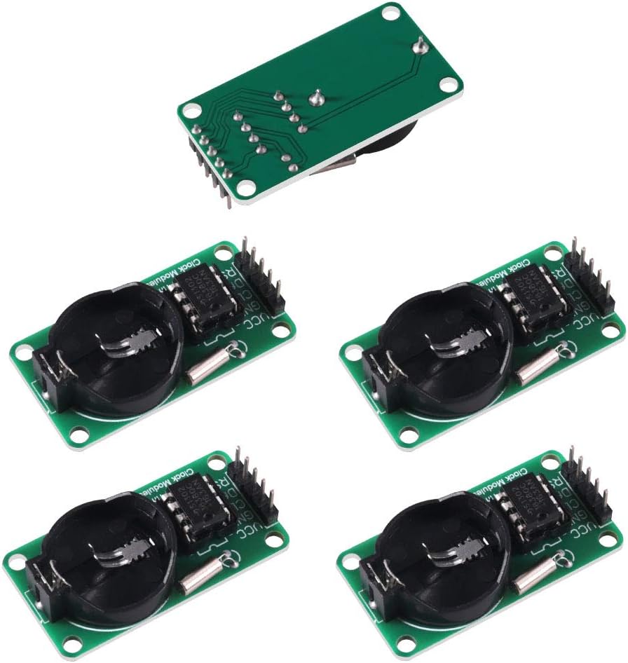
The DS1302 Clock Module consists of the following key components:

- DS1302 IC: The main real-time clock chip responsible for timekeeping and RAM storage.
- Crystal Oscillator: A 32.768 kHz crystal that provides the precise timing reference for the RTC.
- Battery Holder: Designed to hold a CR2032 or LIR2032 coin cell battery, which powers the RTC when the main power supply is off, ensuring continuous timekeeping.
- Pin Headers: Five pins for electrical connections to a microcontroller.
Pinout Description:
- VCC: Power supply input (3.3V or 5V).
- GND: Ground connection.
- CLK: Serial Clock input.
- DAT: Serial Data I/O.
- RST: Reset/Chip Select input.

5. Setup Instructions
5.1. Battery Installation
The DS1302 module requires a coin cell battery (typically CR2032 or LIR2032) to maintain time when the main power supply is disconnected. Carefully insert the battery into the holder with the positive (+) side facing upwards.
Important Battery Note: Some DS1302 modules may include a charging circuit. If your module has a charging circuit, it is designed for rechargeable LIR2032 batteries. Using a non-rechargeable CR2032 battery with an active charging circuit can lead to overheating, leakage, or even explosion. If you intend to use a standard CR2032 battery, ensure the charging circuit (often a resistor or diode) is disabled or removed. Consult the specific module's documentation or manufacturer for details on its battery charging configuration.
5.2. Wiring to a Microcontroller
Connect the DS1302 module to your microcontroller (e.g., Arduino, Raspberry Pi, ESP32) using the following pin assignments:
- VCC – Connect to the microcontroller's 3.3V or 5V power supply.
- GND – Connect to the microcontroller's Ground (GND).
- CLK – Connect to a digital output pin on your microcontroller (e.g., Arduino Digital Pin 5).
- DAT – Connect to a digital I/O pin on your microcontroller (e.g., Arduino Digital Pin 4).
- RST – Connect to a digital output pin on your microcontroller (e.g., Arduino Digital Pin 3).
Note: The specific digital pins (CLK, DAT, RST) can be configured in your software. Refer to your chosen library's documentation for recommended or default pin assignments.
6. Operating Instructions
To operate the DS1302 module, you will typically use a library specific to your microcontroller platform (e.g., Arduino DS1302 library). The general steps involve initializing the module, setting the current time, and then reading the time as needed.
6.1. Software Setup (Example for Arduino)
- Install Library: Open your Arduino IDE, go to Sketch > Include Library > Manage Libraries... Search for "DS1302" and install a suitable library (e.g., "DS1302RTC" or similar).
- Include Library: In your sketch, include the library:
#include <DS1302RTC.h>(or the specific library header). - Define Pins: Define the CLK, DAT, and RST pins you connected:
DS1302RTC rtc(RST_PIN, DAT_PIN, CLK_PIN);
6.2. Setting the Time
After initializing the RTC, you can set the current date and time. This is typically done once, or whenever the time needs to be corrected.
- Use functions provided by the library to set year, month, day, hour, minute, and second. For example, with some libraries, you might create a
DateTimeobject and then write it to the RTC. - Example (conceptual):
rtc.setDateTime(year, month, day, hour, minute, second);
6.3. Reading the Time
Once the time is set, the RTC will keep track of it. You can read the current time and date at any point.
- Use library functions to retrieve individual time components (e.g.,
rtc.getHour(),rtc.getMinute(),rtc.getSecond(),rtc.getYear(), etc.). - The retrieved values can then be displayed on an LCD, sent to a serial monitor, or used for other time-sensitive operations in your project.
7. Maintenance
7.1. Battery Replacement
The coin cell battery provides backup power for the RTC. If the module loses time when the main power is off, the battery may need replacement. To replace the battery:
- Ensure the module is disconnected from the main power supply.
- Carefully remove the old battery from the holder.
- Insert a new, compatible coin cell battery (CR2032 or LIR2032, observing the warning in Section 5.1) with the positive (+) side facing up.
- After replacing the battery, you may need to reset the time on the RTC module.
7.2. General Care
- Keep the module in a dry environment, away from moisture and extreme temperatures.
- Avoid exposing the module to static electricity. Handle it by the edges or use anti-static precautions.
- Do not apply excessive force to the components or pin headers.
8. Troubleshooting
- Module Not Responding:
- Check all wiring connections (VCC, GND, CLK, DAT, RST) for proper contact and correct pin assignments.
- Verify the power supply voltage (3.3V or 5V) is stable.
- Ensure the correct library is installed and initialized in your code.
- Time Drift / Incorrect Time:
- Confirm the battery is correctly installed and has sufficient charge.
- Re-set the time to ensure it was initially programmed correctly.
- Ensure the crystal oscillator is securely attached and undamaged.
- Verify that the module is not exposed to extreme temperature fluctuations, which can affect crystal accuracy.
- Battery Drains Quickly:
- If using a non-rechargeable CR2032, ensure any charging circuit on the module is disabled. Refer to Section 5.1.
- Check for any short circuits or incorrect wiring that might be drawing excessive current.
9. Warranty and Support
For warranty information, technical support, or further assistance, please contact the manufacturer or your point of purchase. Keep your purchase receipt for warranty claims.