1. Introduction
This manual provides essential information for the safe and efficient operation of your Vikye STP6005DH Regulated DC Power Supply. Please read this manual thoroughly before using the device to ensure proper functionality and to prevent damage or injury. This power supply is designed to provide a stable and adjustable DC voltage and current output for various laboratory, testing, and industrial applications.
2. Safety Instructions
Observe the following safety precautions to prevent electric shock, fire, or damage to the device:
- Ensure the power switch (110V/220V) on the rear panel is set to the correct local voltage standard before connecting to mains power. Incorrect voltage selection can cause severe damage to the unit.
- Connect the power supply to a grounded power outlet. Do not defeat the grounding plug.
- Do not operate the power supply in wet or damp conditions.
- Do not open the casing of the power supply. There are no user-serviceable parts inside. Refer all servicing to qualified personnel.
- Ensure adequate ventilation around the unit. Do not block ventilation openings.
- Disconnect power before making or breaking connections to the output terminals.
- Avoid short-circuiting the output terminals for extended periods.
3. Product Overview
The Vikye STP6005DH is a high-performance regulated DC power supply featuring dual LED displays for simultaneous voltage and current readout. It offers continuous adjustment of output voltage and current in both Constant Voltage (CV) and Constant Current (CC) modes. Multiple protection functions are integrated, including current limiting, short-circuit protection, and over-temperature protection.
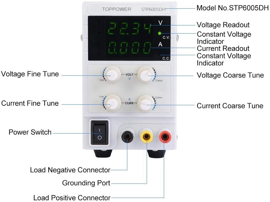
Figure 3.1: Front Panel Layout and Controls
This diagram illustrates the various components on the front panel, including the digital displays for voltage and current, fine and coarse adjustment knobs for both voltage and current, the power switch, and the output terminals (Load Negative, Grounding Port, Load Positive).
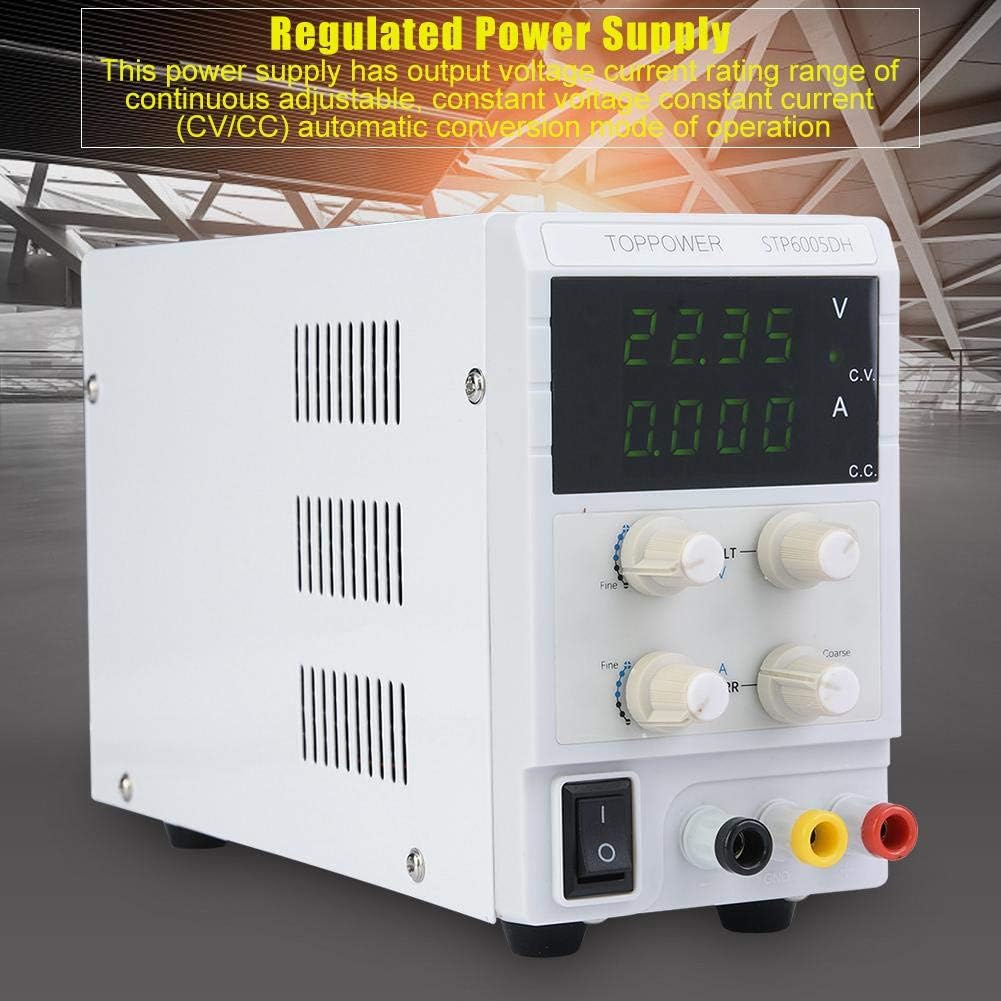
Figure 3.2: Front View of the Power Supply
A general view of the power supply, showing its compact design and the clear digital readouts for voltage and current.
3.1. Components and Controls
- Voltage Readout (V): Digital display for output voltage.
- Current Readout (A): Digital display for output current.
- Constant Voltage (CV) Indicator: Illuminates when the unit is operating in Constant Voltage mode.
- Constant Current (CC) Indicator: Illuminates when the unit is operating in Constant Current mode.
- Voltage Coarse/Fine Tune Knobs: Adjust the output voltage. Use coarse for large changes, fine for precise adjustments.
- Current Coarse/Fine Tune Knobs: Adjust the output current limit. Use coarse for large changes, fine for precise adjustments.
- Power Switch: Turns the unit ON/OFF.
- Output Terminals: Red (Positive), Black (Negative), Yellow/Green (Ground).
4. Setup
4.1. Unpacking and Inspection
Carefully remove the power supply and its accessories from the packaging. Inspect the unit for any signs of damage during transit. If any damage is found, contact your supplier immediately.

Figure 4.1: Included Accessories
The power supply comes with a power cord and a set of test leads for connecting to your load.
4.2. Power Connection
- Locate the voltage selector switch on the rear panel of the power supply.
- Crucially, ensure this switch is set to your local mains voltage (e.g., 110V for US, 220V for EU). Incorrect selection will damage the unit.
- Connect the provided power cord to the AC inlet on the rear panel and then to a grounded mains power outlet.

Figure 4.2: Rear Panel
The rear panel features the AC power inlet and ventilation fan. Ensure the voltage selector switch (not explicitly visible in this image but present on the unit) is correctly set.
4.3. Connecting the Load
Use the provided test leads or appropriate cables to connect your load to the output terminals:
- Connect the positive (+) terminal of your load to the red output terminal of the power supply.
- Connect the negative (-) terminal of your load to the black output terminal of the power supply.
- For safety, connect the grounding port (yellow/green) to the chassis of your load if grounding is required.
Always ensure the power supply is OFF before connecting or disconnecting any load.
5. Operating Instructions
5.1. Initial Power-On and Pre-setting
- Ensure no load is connected to the output terminals.
- Turn the voltage and current coarse adjustment knobs fully counter-clockwise (to minimum).
- Press the Power Switch to turn on the unit. The LED displays will illuminate.
- Adjust the Voltage Coarse and Fine Tune knobs to set the desired output voltage. Observe the Voltage Readout.
- Adjust the Current Coarse and Fine Tune knobs to set the desired current limit. This sets the maximum current the power supply will deliver before switching to Constant Current (CC) mode.
5.2. Connecting the Load and Operation
- Turn off the power supply.
- Connect your load to the output terminals as described in Section 4.3.
- Turn on the power supply.
- The power supply will operate in one of two modes:
- Constant Voltage (CV) Mode: The CV indicator will be lit. The output voltage remains constant at the set value, and the current supplied to the load is determined by the load's resistance, up to the set current limit.
- Constant Current (CC) Mode: The CC indicator will be lit. If the load resistance is too low for the set voltage and current limit, the power supply will automatically switch to CC mode. The output current will be maintained at the set limit, and the output voltage will drop to protect the load.
- Monitor the voltage and current displays during operation.
- To adjust voltage or current during operation, use the respective coarse and fine tune knobs.
5.3. Shutting Down
- Turn off the power supply using the Power Switch.
- Disconnect the load from the output terminals.
- Disconnect the power cord from the mains outlet if the unit will not be used for an extended period.
6. Maintenance
6.1. Cleaning
Regularly clean the exterior of the power supply with a soft, dry cloth. Do not use abrasive cleaners or solvents. Ensure no liquids enter the unit.
6.2. Ventilation
Keep the ventilation openings clear of dust and obstructions to ensure proper airflow and prevent overheating. Periodically check the fan for dust buildup.
6.3. Fuse Replacement
The power supply is equipped with an internal fuse (F5AL, 250VAC). If the unit fails to power on, the fuse may need replacement. This procedure should only be performed by qualified service personnel. Opening the unit by unauthorized individuals voids the warranty.
7. Troubleshooting
| Problem | Possible Cause | Solution |
|---|---|---|
| Unit does not power on. |
|
|
| No output voltage/current. |
|
|
| Unit switches to CC mode unexpectedly. |
|
|
8. Specifications
The following are the technical specifications for the Vikye STP6005DH Regulated DC Power Supply:
| Parameter | Value |
|---|---|
| Model | STP6005DH |
| Working Temperature | 0 ~ 40°C |
| Relative Humidity | ≤80% |
| Fuse | F5AL, 250VAC |
| Output Voltage | 0-60V |
| Voltage Regulation Rate | ≤0.03% + 1mV |
| Load Regulation Rate (Voltage) | ≤0.33% |
| Ripple and Noise (Voltage) | ≤3mVrms (5Hz ~ 1MHz), <10Vppm |
| Output Current | 0-5A |
| Current Regulation Rate | ≤0.1% + 1mA |
| Load Regulation Rate (Current) | ≤0.2% + 5mA |
| Recovery Time | ≤300µs (with 50% regulation rate load, 0.5A) |
| Storage Temperature | -10 ~ 70°C |
| Storage Humidity | ≤70% |
| Input Voltage | 110V / 220V / 230V (selectable) |
| Weight | Approx. 1.6 kg (56.4 oz) |
| Dimensions (L x W x H) | 226 x 82 x 138 mm (8.9 x 3.2 x 5.4 in) |
| Output Power | 300 Watts |
| Amperage | 5 A |
| UPC | 739904172079 |
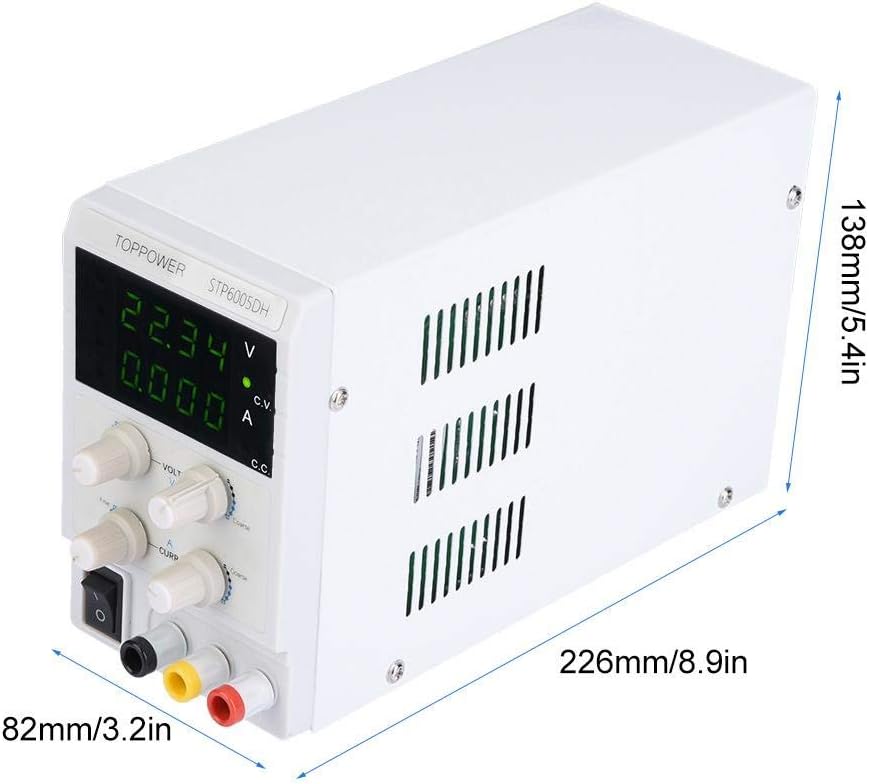
Figure 8.1: Product Dimensions
This image provides the physical dimensions of the power supply unit.
9. Warranty and Support
For warranty information and technical support, please refer to the documentation provided with your purchase or contact the manufacturer directly. Keep your purchase receipt as proof of purchase for warranty claims.
Manufacturer: Vikye