Introduction
This user manual provides detailed instructions for the Walfront STC-1000 Digital Temperature Controller. This device is a microcomputer intelligent digital display thermostat designed for precise temperature control in various applications, including refrigeration and heating systems.
The STC-1000 features an ABS flame retardant plastic shell for safety and durability, a clear digital display for easy monitoring, and a 1-meter sensor for convenient usage. It is suitable for automatic switching of refrigeration and heating devices such as seafood machines and cooling water machines.

Image: Front view of the Walfront STC-1000 Digital Temperature Controller, showing the digital display, control buttons, and wiring diagram label.
Specifications
| Feature | Detail |
|---|---|
| Model | Walfronte780p34qfv-3 (STC-1000) |
| Voltage | 110~240VAC |
| Material | ABS flame retardant plastic shell |
| Item Weight | 3.34 ounces |
| Sensor Cable Length | Approximately 1 meter |
| UPC | 713135327217 |
Setup and Installation
Proper installation is crucial for the safe and effective operation of the STC-1000 temperature controller. Please follow the wiring diagram carefully.
Wiring Instructions:
- Power Supply: Connect the 110-220VAC power supply to terminals 1 (Live, L) and 2 (Neutral, N).
- Sensor Connection: Connect the temperature sensor to terminals 3 and 4. Ensure proper polarity if applicable, though typically NTC sensors are non-polar.
- Heating Output: For heating applications, connect the heating device to terminals 5 and 6. Terminal 5 is the common relay output, and terminal 6 is the normally open (NO) contact for heating.
- Cooling Output: For cooling applications, connect the cooling device to terminals 7 and 8. Terminal 7 is the common relay output, and terminal 8 is the normally open (NO) contact for cooling.
- Important Note: Strictly distinguish the interface of the relay, sensor, and power supply. Ensure the sensor probe and power wire are kept at a proper distance to avoid interference.

Image: Detailed wiring diagram for the STC-1000, showing connections for power supply, sensor, heating load, and cooling load. Two common wiring configurations are depicted.
Before powering on the device, double-check all connections to ensure they are secure and correctly wired according to the diagram.
Operating Instructions
The STC-1000 features a user-friendly interface for setting and monitoring temperature.
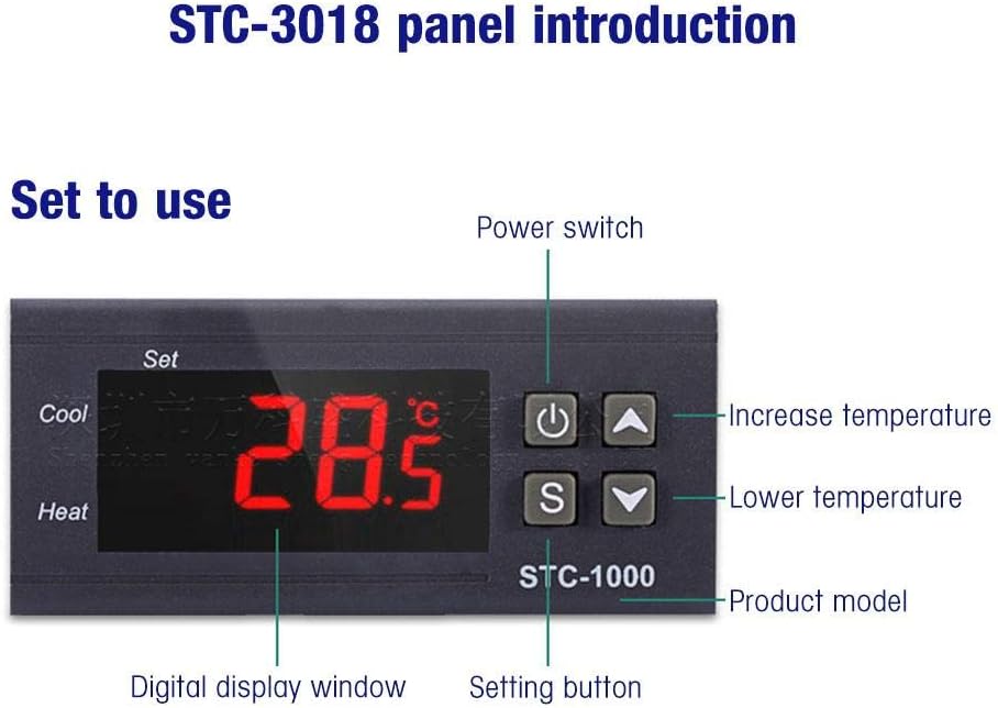
Image: Front panel of the STC-1000 showing the digital display window, power switch, setting button, and temperature adjustment buttons (increase/decrease).
Panel Introduction:
- Digital Display Window: Shows the current measured temperature.
- Power Switch (⏻): Turns the device on or off.
- Setting Button (S): Used to enter and confirm parameter settings.
- Increase Temperature Button (▲): Increases the set temperature value or navigates through menu options.
- Lower Temperature Button (▼): Decreases the set temperature value or navigates through menu options.
Setting Temperature Parameters:
- To View Set Temperature: Briefly press the 'S' button. The display will show the current set temperature. Press 'S' again or wait a few seconds to return to the current temperature display.
- To Modify Set Temperature: Press and hold the 'S' button for approximately 3 seconds until the display flashes. Use the '▲' (up) and '▼' (down) buttons to adjust the desired temperature. Press 'S' again to confirm and save the new setting.
- Accessing Advanced Settings (P0-P3): Press and hold the 'S' button for approximately 3 seconds. While the set temperature is flashing, press the 'S' button again to cycle through the parameter codes (P0, P1, P2, P3). Use '▲' and '▼' to adjust the values for each parameter. Press 'S' to confirm each parameter setting.
Common Parameters:
- P0: Heating/Cooling Mode (C for Cooling, H for Heating).
- P1: Hysteresis Setting (Temperature difference for relay activation).
- P2: Upper Limit of Set Temperature.
- P3: Lower Limit of Set Temperature.
Maintenance
To ensure the longevity and accurate performance of your Walfront STC-1000 Digital Temperature Controller, follow these maintenance guidelines:
- Cleaning: Regularly wipe the exterior of the controller with a soft, dry cloth. Do not use abrasive cleaners or solvents, as they may damage the plastic casing or display.
- Sensor Care: Keep the temperature sensor clean and free from debris. Ensure it is not exposed to extreme physical stress or corrosive environments unless specifically designed for such conditions.
- Connection Checks: Periodically inspect all wiring connections to ensure they remain secure. Loose connections can lead to inaccurate readings or device malfunction.
- Environmental Conditions: Operate the controller within its specified environmental limits (temperature, humidity) to prevent damage. Avoid direct exposure to water or excessive dust.
- Power Off Before Maintenance: Always disconnect the power supply to the controller before performing any cleaning or inspection to prevent electrical shock.
Troubleshooting
This section provides solutions to common issues you might encounter with your STC-1000 Digital Temperature Controller.
| Problem | Possible Cause | Solution |
|---|---|---|
| Display shows "LLL" or "HHH" | Sensor error (open circuit or short circuit) or temperature out of range. | Check sensor wiring connections (terminals 3 & 4). Replace sensor if damaged. Ensure temperature is within the controller's measurable range. |
| Controller not powering on | No power supply or incorrect wiring. | Verify power supply (110-220VAC) is connected to terminals 1 & 2. Check power switch. Ensure wiring is correct and secure. |
| Heating/Cooling device not activating | Incorrect temperature settings, wrong mode (P0), or faulty wiring to load. | Check set temperature and hysteresis (P1). Ensure P0 is set correctly (C for cooling, H for heating). Verify wiring to heating/cooling device (terminals 5-6 or 7-8). Test the load device independently. |
| Temperature reading is inaccurate | Sensor placement, interference, or damaged sensor. | Relocate sensor to a representative area. Ensure sensor wire is away from power lines. Replace sensor if suspected faulty. |
Warranty and Support
Walfront is committed to providing quality products. While specific warranty details are not provided in this manual, please refer to your purchase documentation or contact Walfront customer support for warranty information and technical assistance.
For further support, you may visit the official Walfront store or contact their customer service channels as provided at the time of purchase.
Walfront Official Store: Visit Walfront Store on Amazon


