1. Introduction
The YMDK Skyloong GK64XS is a versatile 64-key hot-swappable Printed Circuit Board (PCB) designed for custom mechanical keyboards. It supports both wired (Type-C) and Bluetooth connectivity, offering flexibility for various setups. This PCB features per-switch RGB lighting and includes a connector for an optional underglow RGB strip, allowing for extensive lighting customization. It is fully programmable via dedicated software, enabling users to personalize key assignments and macros.
This manual provides essential information for setting up, operating, and maintaining your GK64XS Bluetooth PCB, ensuring optimal performance and longevity.
2. Product Features
- Dual Connectivity: Supports both wired (USB Type-C) and Bluetooth wireless connections.
- Hot-Swappable Sockets: Allows for easy installation and removal of mechanical switches without soldering.
- Per-Switch RGB Lighting: Individual RGB LEDs under each switch for customizable backlighting effects.
- Underglow RGB Support: Includes an insert pin for connecting an optional underglow RGB strip (sold separately).
- Fully Programmable: Customize key functions, macros, and lighting effects using the dedicated software.
- Flexible Layout: Supports standard 6.25u spacebar as well as split 2.25u and 2.75u space layouts.
- Advanced Chipset: Equipped with a 32-bit MCU and 8M Flash memory, supporting 16.8 million RGB colors.
- Pre-soldered Battery Hole: Facilitates easy installation of a compatible battery for Bluetooth operation.
3. Setup Guide
3.1 Unpacking and Inspection
Carefully remove the GK64XS PCB from its packaging. Inspect the board for any visible damage or missing components. Ensure all necessary accessories, such as the USB Type-C cable, are present.
3.2 Battery Installation (for Bluetooth Models)
For Bluetooth functionality, a battery is required. The PCB features a pre-soldered battery hole. Please prepare a battery with a 2-pin 1.25mm connector. Ensure the wire sequence is Red (positive) and Black (negative) to match the PCB's polarity. Insert the battery into the designated slot and connect it to the PCB.
3.3 Switch Installation
The GK64XS PCB features hot-swappable sockets. Align the pins of your mechanical switches with the holes on the PCB and gently press them into place until they click. Ensure the switches are fully seated and straight.
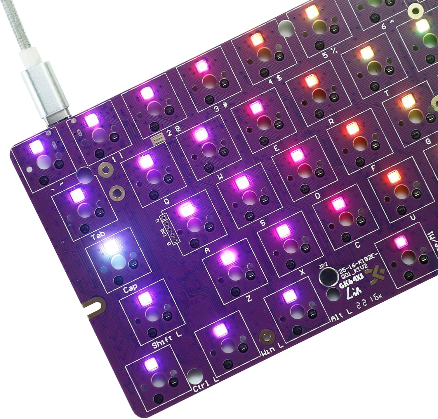
Image: Top view of the GK64XS PCB with switches installed and RGB lighting active, connected via USB-C.
3.4 Case Compatibility
This PCB is designed to be compatible with most GH60 size keyboard cases and plates. Ensure your chosen case and plate support the 64-key layout and the specific mounting points of the GK64XS.

Image: Layout diagram illustrating the GK64XS's support for various spacebar configurations, including split space options.
3.5 Software Installation
To fully customize your GK64XS PCB, download and install the official programming software. The software can be found at: drive.google.com/open?id=1NQxMtKlI5PnjdT355soHQ4GN_JoaRMLT. Follow the on-screen instructions for installation.
4. Operating Instructions
4.1 Wired Mode Connection
Connect the GK64XS PCB to your computer using a USB Type-C cable. The PCB will be automatically recognized by your operating system. No drivers are typically required for basic functionality.
4.2 Bluetooth Mode Pairing
- Ensure a compatible battery is installed and charged.
- Turn on the Bluetooth function on your computer or device.
- Put the GK64XS PCB into pairing mode (refer to the software or quick start guide for specific key combinations, often Fn + a specific key).
- On your device, search for new Bluetooth devices and select 'GK64XS' or a similar identifier.
- Follow any on-screen prompts to complete the pairing process.
4.3 Layout Programming
Utilize the dedicated software to customize your keyboard layout. You can remap keys, create macros, and configure different layers. Note: The 'Fn' key is fixed at the right of the bottom row and its position cannot be changed through the software.
4.4 RGB Lighting Control
The per-switch RGB lighting can be controlled and customized via the programming software. You can select various lighting effects, colors, and brightness levels. If an underglow RGB strip is installed, its lighting can also be managed through the software.
5. Maintenance
5.1 Cleaning
To clean the PCB, ensure it is disconnected from power. Use a soft, dry brush or compressed air to remove dust and debris. For stubborn grime, a cotton swab lightly dampened with isopropyl alcohol can be used, ensuring the PCB is completely dry before reconnecting power.
5.2 Storage
When not in use, store the PCB in a dry, cool environment away from direct sunlight and extreme temperatures. If storing for an extended period, consider removing the battery to prevent potential leakage.
6. Troubleshooting
6.1 Connectivity Issues
- Wired Connection Not Detected: Try a different USB Type-C cable and port. Ensure the cable is fully inserted. Test on another computer if possible.
- Bluetooth Pairing Failure: Ensure the battery is charged. Confirm the PCB is in pairing mode. Remove previous pairings from your device and try again. Ensure no other Bluetooth devices are interfering.
6.2 Key Functionality Problems
- Keys Not Responding: Check if switches are fully seated in their hot-swap sockets. Try swapping the problematic switch with a known working one to isolate if the issue is with the switch or the socket.
- Unexpected Key Output: Reset the PCB to factory settings via the software if available. Re-flash your custom layout.
6.3 Software and Firmware Issues
- Programming Not Applying: Ensure the software is running with administrator privileges. Verify the PCB is connected and recognized by the software before attempting to flash.
- Software Crashes: Reinstall the software. Check for updated versions on the official website.
6.4 Physical Fit Issues
In some rare instances, the PCB dimensions might vary slightly, potentially causing fitment issues with certain cases. If the PCB does not fit your case, carefully compare its dimensions with your case's specifications. Avoid forcing the PCB into a case, as this may cause damage.
7. Specifications
| Product Dimensions | 11.81 x 5.91 x 0.79 inches |
| Item Weight | 7 ounces |
| Manufacturer | WPL |
| Item Model Number | GK-64-Ble-PCB |
| Connectivity Technology | Bluetooth, USB Type-C (Wired) |
| Compatible Devices | PC |
| Keyboard Description | Bluetooth Mechanical Keyboard PCB |
| Special Feature | Waterproof (PCB coating) |
| Color | GK64XS Bluetooth (PCB color may vary) |
| Keyboard Backlighting Color Support | RGB (16.8 million colors) |
| Material | Plastic (PCB substrate) |
8. Support
For further assistance, software updates, or detailed technical support, please visit the official YMDK website or contact their customer service. The programming software can be downloaded from: drive.google.com/open?id=1NQxMtKlI5PnjdT355soHQ4GN_JoaRMLT.


