
1. Introduction
The BSIDE ZT109 is a portable, True RMS digital multimeter designed for professional and practical use. It features a large 9999-count LCD with backlight, offering clear readability. This device is capable of measuring AC/DC voltage, AC/DC current, resistance, capacitance, frequency, diode, and continuity. Its robust design includes strong anti-interference capabilities and an auto power-off function after 15 minutes of inactivity to conserve battery life.
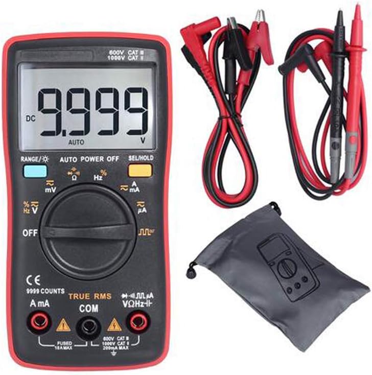
Figure 1: BSIDE ZT109 Digital Multimeter with included accessories.
2. Safety Information
To ensure safe operation and service of the multimeter, please read all instructions carefully before use. Failure to observe these safety warnings may result in electric shock, injury, or damage to the meter or equipment under test.
- Always ensure the test leads are properly connected and the function switch is set to the correct range before making any measurements.
- Do not apply voltage or current that exceeds the maximum specified limits for the meter.
- Exercise extreme caution when working with voltages above 30V AC RMS, 42V peak, or 60V DC. These voltages pose a shock hazard.
- Before measuring resistance, continuity, or diode, ensure that the circuit under test is de-energized and all capacitors are discharged.
- Replace the battery immediately when the low battery indicator appears to ensure accurate readings.
- Do not operate the meter if it appears damaged or if the case is open.
- Use only the specified replacement parts when servicing the meter.
3. Product Overview
Familiarize yourself with the components of your BSIDE ZT109 Digital Multimeter.

Figure 2: Front panel components including LED display, range button, function switch key, rotary switch, and input sockets.

Figure 3: Close-up view highlighting the display screen, input jacks, and function selection button.
The multimeter features a large LCD display, a rotary switch for selecting measurement functions, and buttons for range, backlight, and data hold. The input sockets are clearly labeled for current (mA/A), common (COM), and voltage/resistance/diode/capacitance (VΩHz™).
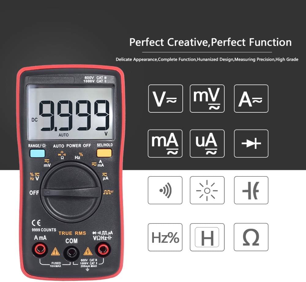
Figure 4: Overview of measurement capabilities indicated by symbols on the display.
4. Setup
4.1 Battery Installation
The BSIDE ZT109 multimeter requires two 1.5V AAA batteries for operation. Ensure the batteries are installed correctly before first use or when replacing them.
- Turn off the multimeter and disconnect all test leads.
- Locate the battery compartment cover on the back of the unit.
- Use a screwdriver to loosen the screw securing the battery cover.
- Remove the cover and insert two 1.5V AAA batteries, observing the correct polarity (+ and -).
- Replace the battery cover and tighten the screw.
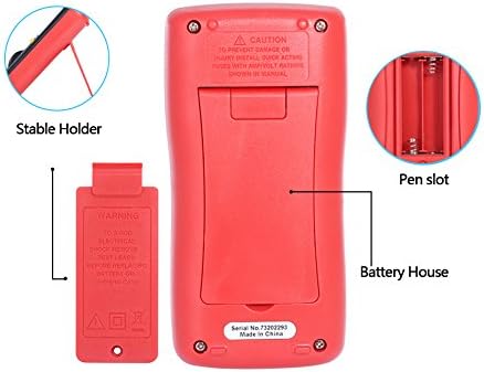
Figure 5: Rear view of the multimeter, illustrating the battery compartment and integrated stable holder.
4.2 Connecting Test Leads
Always connect the black test lead to the COM (common) input jack. Connect the red test lead to the appropriate input jack based on the measurement type:
- For voltage, resistance, capacitance, frequency, and diode measurements, connect the red lead to the VΩHz™ input jack.
- For current measurements (mA or A), connect the red lead to the mA/A input jack.
5. Operating Instructions
5.1 Power On/Off and Auto Power Off
To turn on the multimeter, rotate the function switch from the 'OFF' position to any desired measurement function. The meter will automatically power off after approximately 15 minutes of inactivity to conserve battery life. To disable auto power off, press and hold the 'SEL/HOLD' button while turning the meter on.
5.2 Measurement Functions
Select the desired measurement function using the rotary switch. Use the 'RANGE' button to switch between auto-ranging and manual-ranging modes, and the 'SEL/HOLD' button to select sub-functions (e.g., AC/DC, diode/continuity) or to hold the current reading on the display.
5.2.1 DC Voltage Measurement (V)
- Set the rotary switch to the 'V™' position.
- Connect the black test lead to the COM jack and the red test lead to the VΩHz™ jack.
- Connect the test leads across the DC voltage source to be measured.
- Read the voltage value on the display.
5.2.2 AC Voltage Measurement (V)
- Set the rotary switch to the 'V™' position.
- Press the 'SEL/HOLD' button to switch to AC voltage measurement if necessary.
- Connect the black test lead to the COM jack and the red test lead to the VΩHz™ jack.
- Connect the test leads across the AC voltage source to be measured.
- Read the voltage value on the display.
5.2.3 DC/AC Current Measurement (mA & A)
- Set the rotary switch to the 'mA™' or 'A™' position depending on the expected current.
- Press the 'SEL/HOLD' button to switch between DC and AC current measurement if necessary.
- Connect the black test lead to the COM jack and the red test lead to the mA/A jack.
- Important: Connect the multimeter in series with the circuit to measure current. Do not connect it in parallel across a voltage source.
- Read the current value on the display.
5.2.4 Resistance Measurement (Ω)
- Set the rotary switch to the 'Ω' position.
- Ensure the circuit under test is de-energized and all capacitors are discharged.
- Connect the black test lead to the COM jack and the red test lead to the VΩHz™ jack.
- Connect the test leads across the component to measure its resistance.
- Read the resistance value on the display.
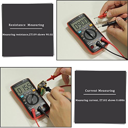
Figure 6: Example of measuring resistance using the ZT109 multimeter.
5.2.5 Capacitance Measurement (F)
- Set the rotary switch to the '™F' position.
- Ensure the capacitor is fully discharged before measurement.
- Connect the black test lead to the COM jack and the red test lead to the VΩHz™ jack.
- Connect the test leads across the capacitor.
- Read the capacitance value on the display.
5.2.6 Frequency Measurement (Hz)
- Set the rotary switch to the 'Hz%' position.
- Connect the black test lead to the COM jack and the red test lead to the VΩHz™ jack.
- Connect the test leads across the signal source.
- Read the frequency value on the display.
5.2.7 Diode Test (→|→)
- Set the rotary switch to the '→|→' position.
- Press the 'SEL/HOLD' button to select the diode test function.
- Connect the black test lead to the COM jack and the red test lead to the VΩHz™ jack.
- Connect the red test lead to the anode and the black test lead to the cathode of the diode.
- The display will show the forward voltage drop. Reverse the leads; the display should show 'OL' (open loop) for a good diode.
5.2.8 Continuity Test (™))
- Set the rotary switch to the '→|→' position.
- Press the 'SEL/HOLD' button to select the continuity test function.
- Connect the black test lead to the COM jack and the red test lead to the VΩHz™ jack.
- Connect the test leads across the circuit or component.
- If the resistance is below approximately 50Ω, the buzzer will sound, indicating continuity.
6. Maintenance
6.1 Cleaning
Wipe the case with a damp cloth and a mild detergent. Do not use abrasives or solvents. Ensure the meter is completely dry before use.
6.2 Battery Replacement
Refer to Section 4.1 for detailed instructions on battery replacement. Always replace both batteries with new 1.5V AAA batteries when the low battery indicator appears.
6.3 Fuse Replacement
The multimeter is protected by internal fuses. If the current measurement function stops working, the fuse may need replacement. Fuse replacement should only be performed by qualified personnel. Use only fuses with the specified ratings (e.g., FUSED 10A MAX, FUSED 200mA MAX as indicated near the input sockets).
6.4 Storage
If the meter is not to be used for an extended period, remove the batteries to prevent leakage and damage to the device. Store the multimeter in a cool, dry place, away from direct sunlight and extreme temperatures.
7. Troubleshooting
- Meter does not power on: Check battery installation and ensure batteries are not depleted. Replace if necessary.
- No reading or 'OL' (Overload) displayed: Ensure test leads are correctly connected and making good contact. Verify the function switch is set to the correct range. If measuring resistance or continuity, ensure the circuit is de-energized. 'OL' can also indicate a value exceeding the meter's range.
- Inaccurate readings: Check battery level. Ensure test leads are not damaged. Verify the correct function and range are selected.
- Current measurement not working: Check the fuse. If blown, it needs to be replaced by a qualified technician with a fuse of the correct rating.
8. Specifications
| Parameter | Range / Value | Accuracy |
|---|---|---|
| DC Voltage (V) | 999.9mV - 999.9V | (0.5% +3) |
| DC Voltage (mV) | 9.999mV - 99.99mV | (0.5% +3) |
| AC Voltage (V) | 9.999mV - 750V | (1% +3) |
| AC Voltage (mV) | 9.999mV - 99.99mV | (1% +3) |
| DC Current (mA & A) | 999.9mA - 9.999A | (1% +3) |
| DC Current (ℬ) | 99.99ℬ - 999.9ℬ | (0.8% +3) |
| AC Current (mA & A) | 999.9mA - 9.999A | (1.2% +3) |
| AC Current (ℬ) | 99.99ℬ - 999.9ℬ | (1.0% +3) |
| Resistance | 99.99Ω - 9.999MΩ | (0.5% +3) |
| Capacitance | 9.999nF - 9.999mF | (2.0% +5) |
| Frequency | 99.99Hz - 9.999MHz | (0.1% +2) |
| Diode | Yes | N/A |
| Continuity | Yes | N/A |
| Max Display | 9999 Counts | N/A |
| Ranging | Auto/Manual | N/A |
| Operating Temperature | 0℃ ~ 40℃ | N/A |
| Storage Temperature | -20℃ ~ 60℃ | N/A |
| Power Supply | 2* 1.5V AAA Battery | N/A |
| Dimensions | 130mm x 65mm x 32mm | N/A |
| Weight | Approx. 130g (without batteries) | N/A |

Figure 7: Physical dimensions of the BSIDE ZT109 multimeter.
9. Warranty and Support
For warranty information and technical support, please refer to the documentation provided with your purchase or contact the seller directly. Keep your proof of purchase for any warranty claims.


