1. Introduction
This manual provides detailed instructions for the installation, operation, and maintenance of the ACEIRMC TPA3116D2 XH-M543 Dual Channel Stereo Digital Audio Power Amplifier Board. This module is designed for DIY audio projects, offering high-power stereo amplification suitable for various applications including car audio systems, computer speakers, and home theater setups. Please read this manual thoroughly before use to ensure proper functionality and safety.
2. Safety Information
- Power Supply: Ensure the power supply voltage is within the specified range (DC 12V-26V). Using an incorrect voltage can damage the board.
- Polarity: Always observe correct polarity when connecting the power supply. Reverse polarity will cause immediate damage.
- Connections: Make all connections (power, audio input, speaker output) before applying power to the board.
- Heat: The amplifier board generates heat during operation. Ensure adequate ventilation and do not cover the heatsink.
- Moisture: Keep the board away from water, moisture, and conductive liquids.
- Handling: Handle the board by its edges to avoid touching components, especially when powered.
3. Package Contents
Verify that all items are present in your package:
- 1 x ACEIRMC TPA3116D2 XH-M543 Audio Amplifier Board
- 1 x Audio Cable
4. Product Overview
The ACEIRMC TPA3116D2 XH-M543 is a compact and powerful Class D digital audio amplifier board. It features the TPA3116D2 chip, known for its efficiency and sound quality. The board includes onboard potentiometers for independent left and right channel volume control, and robust terminal blocks for secure connections.
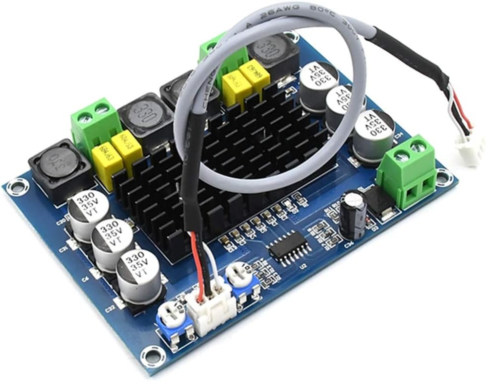
Figure 4.1: Overall view of the amplifier board, showcasing its compact design and main components including the heatsink and terminal blocks.

Figure 4.2: Detailed top-down view of the amplifier board, highlighting the various electronic components and the central heatsink for thermal management.
5. Specifications
| Feature | Specification |
|---|---|
| Model Number | XH-M543 |
| Chip | TPA3116D2 |
| Supply Voltage | DC 12V - 26V |
| Minimum Supply Voltage | 12 Volts (DC) |
| Maximum Supply Voltage | 26 Volts (DC) |
| Number of Channels | 2 (Stereo) |
| Total Output Power | 240 Watts (120W + 120W) |
| Mounting Type | Surface Mount |
| Item Weight | 2.78 ounces |
| Package Dimensions | 5.24 x 4.72 x 0.79 inches |
6. Setup Instructions
Follow these steps to correctly set up your amplifier board:

Figure 6.1: Connection diagram for the amplifier board, showing input and output terminals.
- Power Supply Connection:
- Locate the power input terminals (labeled VCC and GND, typically on the right side of the board as shown in Figure 6.1).
- Connect a DC power supply (12V-26V) to these terminals. Ensure the positive (+) wire connects to VCC and the negative (-) wire connects to GND. Incorrect polarity will damage the board.
- Audio Input Connection:
- Identify the 3P audio input connector (typically on the bottom left, labeled '3P audio input' in Figure 6.1).
- Connect your audio source (e.g., smartphone, MP3 player, computer) to this input using the provided audio cable or a suitable 3-pin connector. The pins are typically Left, GND, Right.
- Speaker Output Connection:
- Locate the left and right channel speaker output terminals (typically on the top of the board, labeled 'left channel output' and 'right channel output' in Figure 6.1).
- Connect your speakers to these terminals. Ensure correct polarity for each speaker (+ to + and - to -) for optimal sound quality.
- Volume Adjustment:
- The board features two potentiometers for independent volume adjustment of the left and right channels (labeled 'left volume adjust' and 'right volume adjust' in Figure 6.1).
- Turn these knobs to control the output volume.
7. Operating Instructions
- After completing all connections as described in Section 6, apply power to the amplifier board.
- Start playing audio from your connected source.
- Adjust the left and right volume potentiometers on the board to achieve your desired sound level.
- Ensure the audio source volume is also set to an appropriate level to avoid distortion.
8. Maintenance
- Cleaning: Use a soft, dry cloth to clean the board. Avoid using liquids or solvents.
- Environment: Store and operate the board in a dry, dust-free environment with good ventilation.
- Inspection: Periodically inspect connections for looseness or corrosion.
- Thermal Management: Ensure the heatsink remains clear of obstructions to allow for proper heat dissipation.
9. Troubleshooting
- No Sound Output:
- Check if the power supply is correctly connected and providing the specified voltage (12V-26V DC).
- Verify that the audio input cable is securely connected to both the source and the amplifier board.
- Ensure speakers are correctly wired to the output terminals and are functional.
- Check if the volume potentiometers on the board are turned up.
- Confirm the audio source is playing and its volume is not muted or too low.
- Distorted Sound:
- Reduce the input volume from your audio source.
- Ensure the power supply is stable and within the recommended voltage range. An underpowered or unstable supply can cause distortion.
- Check speaker impedance. Ensure it is compatible with the amplifier (typically 4-8 ohms).
- Inspect all connections for loose wires or short circuits.
- Overheating:
- Ensure the heatsink is not obstructed and there is sufficient airflow around the board.
- Verify that the speaker load impedance is not too low, which can cause the amplifier to work harder and generate more heat.
- Reduce the output volume if operating at very high levels for extended periods.
10. Warranty and Support
For warranty information or technical support, please contact the seller or manufacturer directly through your purchase platform. Provide your order details and a clear description of the issue for efficient assistance.


