1. Important Safety Information
WARNING: RISK OF ELECTRIC SHOCK. Improper installation can result in serious injury or death. Always turn off power at the circuit breaker or fuse box before wiring. Consult a qualified electrician if you are unsure about any part of these instructions.
- Always turn off power at the service panel before working with electrical wiring.
- Use only with copper or copper-clad wire. Do not use with aluminum wire.
- Ensure all wire connections are secure.
- This device is rated for 15A/120V for the switch and 15A/125V for the receptacle. Do not exceed these ratings.
- Install in accordance with all national and local electrical codes.
2. Package Contents
- BESTTEN Combination Wall Light Switch and Decor Outlet
- Mounting Screws
- Wall Plate
3. Specifications
| Feature | Specification |
|---|---|
| Model Number | GPRS-15A-B2 |
| Switch Type | Single Pole Rocker Switch |
| Switch Rating | 15A/120V |
| Receptacle Type | Decorator Receptacle |
| Receptacle Rating | 15A/125V |
| Wiring Type | Side Wire Only (up to 12 AWG copper or copper clad wire) |
| Material | Polycarbonate (PC) |
| Dimensions | 4.53 x 1.18 x 2.76 inches |
| Certifications | UL Listed |

Image 3.1: Product Dimensions. This diagram illustrates the physical measurements of the combination switch and outlet, along with its included wall plate, in both inches and centimeters.
4. Installation Instructions
4.1. Preparation
- Turn off power: Locate the circuit breaker or fuse that supplies power to the outlet box where you will be installing the device. Turn it off. Verify power is off using a voltage tester.
- Remove old device: Carefully remove the existing wall plate and old switch/outlet from the wall box. Disconnect the wires.
- Inspect wiring: Ensure the electrical box contains the necessary wires: Hot (usually black), Neutral (usually white), and Ground (usually bare copper or green).
4.2. Wiring Configurations
The BESTTEN Combination Switch and Outlet supports various wiring configurations. Refer to the diagram below for visual guidance.
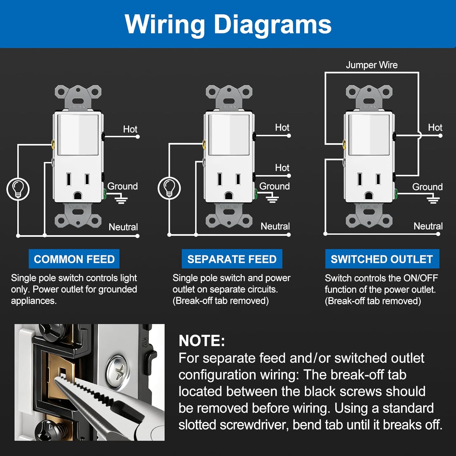
Image 4.1: Wiring Diagrams. This image displays three common wiring scenarios: Common Feed, Separate Feed, and Switched Outlet, detailing how to connect Hot, Ground, and Neutral wires for each. It also includes an important note on removing the break-off tab for specific configurations.
4.2.1. Common Feed (Switch controls light only, outlet is always on)
- Connect the incoming Hot wire to one of the brass screws (line side).
- Connect the outgoing Hot wire to the light fixture to the other brass screw (load side).
- Connect all Neutral wires (incoming and outgoing to light/outlet) to the silver screw(s).
- Connect all Ground wires to the green ground screw.
4.2.2. Separate Feed (Switch and outlet on separate circuits)
IMPORTANT: For this configuration, the break-off tab located between the two brass screws must be removed. Use a standard slotted screwdriver to bend the tab until it breaks off.
- Remove the break-off tab between the brass screws.
- Connect the Hot wire for the switch circuit to one brass screw.
- Connect the Hot wire for the outlet circuit to the other brass screw.
- Connect all Neutral wires to the silver screw(s).
- Connect all Ground wires to the green ground screw.
4.2.3. Switched Outlet (Switch controls the ON/OFF function of the power outlet)
IMPORTANT: For this configuration, the break-off tab located between the two brass screws must be removed. Use a standard slotted screwdriver to bend the tab until it breaks off.
- Remove the break-off tab between the brass screws.
- Connect the incoming Hot wire to one brass screw.
- Connect a short jumper wire from the other brass screw to the brass screw on the outlet side.
- Connect all Neutral wires to the silver screw(s).
- Connect all Ground wires to the green ground screw.
4.3. Final Steps
- Mount the device: Carefully fold the wires into the electrical box. Secure the combination switch and outlet to the box using the provided mounting screws.
- Install wall plate: Attach the included wall plate over the device.
- Restore power: Turn the power back on at the circuit breaker or fuse box.
- Test: Test the functionality of both the switch and the outlet.
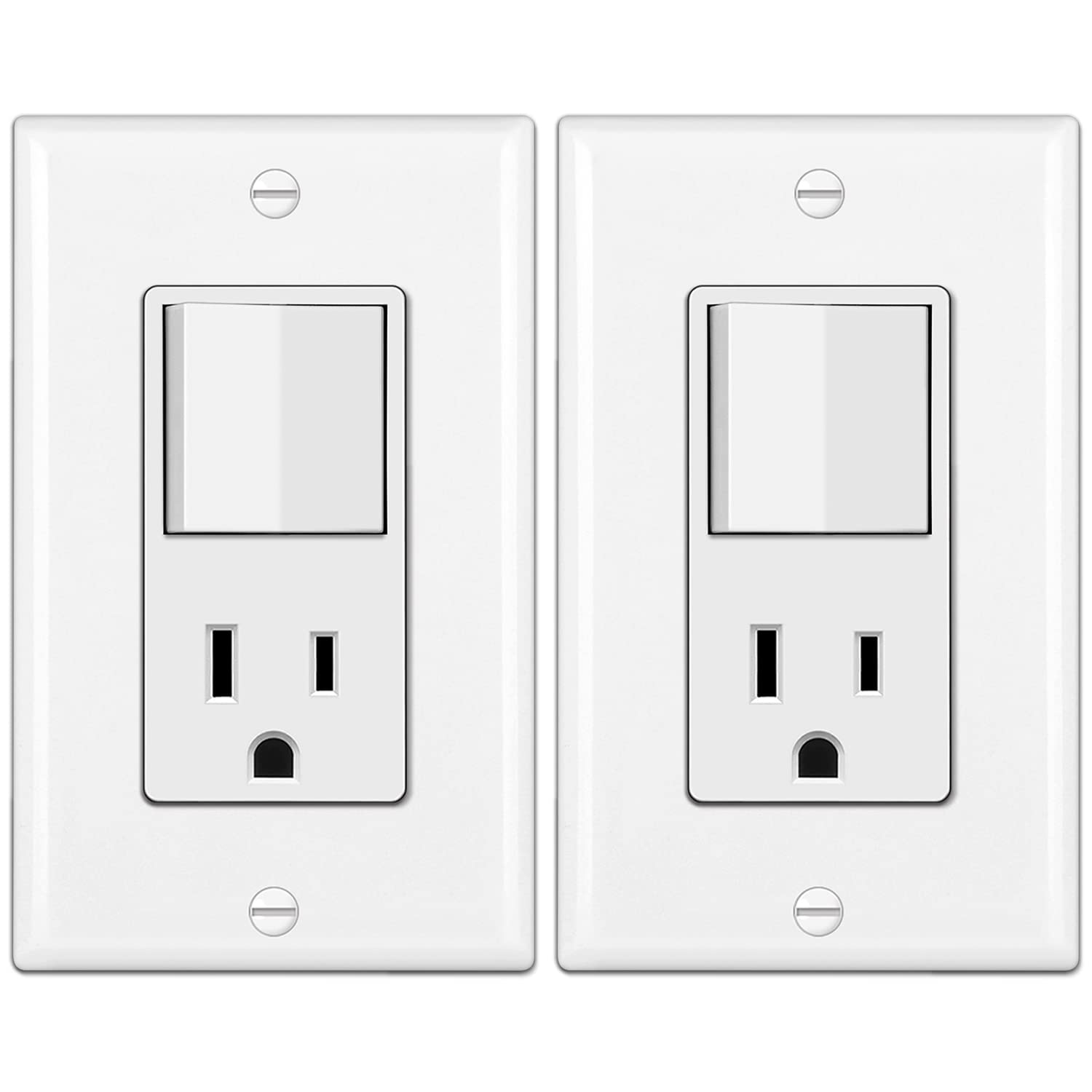
Image 4.2: Front view of the BESTTEN Combination Wall Light Switch and Decor Outlet, showing the rocker switch and the two-prong outlet.

Image 4.3: Space-Saving Design. This image shows the combination unit installed in a kitchen setting, highlighting how it integrates both a switch and an outlet into a single wall plate, optimizing space.
5. Operation
The BESTTEN Combination Wall Light Switch and Decor Outlet functions as two distinct units within a single device:
- Rocker Switch: Press the top or bottom of the rocker switch to turn the connected light fixture or device ON or OFF.
- Decorator Receptacle: Insert a standard 2-prong or 3-prong plug into the outlet to power electrical devices. The functionality of the outlet (always on or switched) depends on the wiring configuration chosen during installation.
6. Maintenance
This device requires minimal maintenance. Follow these guidelines to ensure proper function and longevity:
- Cleaning: To clean the device and wall plate, wipe with a soft, damp cloth. Do not use abrasive cleaners or solvents. Ensure power is off before cleaning.
- Periodic Inspection: Periodically check the device and wall plate for any signs of damage, such as cracks, discoloration, or loose connections. If any damage is observed, turn off power and replace the device.
7. Troubleshooting
If you experience issues with your BESTTEN Combination Switch and Outlet, consider the following:
- No Power to Switch or Outlet:
- Check the circuit breaker or fuse. Ensure it is in the ON position.
- Verify all wire connections are secure. Loose connections can prevent power flow.
- Ensure the incoming power line is correctly identified and connected to the appropriate terminal.
- Switch Not Controlling Light/Outlet:
- Confirm the wiring configuration matches your desired function (Common Feed, Separate Feed, or Switched Outlet).
- If using Separate Feed or Switched Outlet, ensure the break-off tab between the brass screws has been removed.
- Verify the load wire for the light or switched outlet is correctly connected to the switch terminal.
- Outlet Not Providing Power (when switch is ON for switched outlet):
- Check if the device plugged into the outlet is functioning correctly.
- Ensure the neutral wire is properly connected.
If troubleshooting steps do not resolve the issue, consult a qualified electrician.
8. Warranty and Support
BESTTEN products are manufactured to high-quality standards. For specific warranty information or technical support, please refer to the documentation included with your purchase or visit the official BESTTEN website. You may also contact BESTTEN customer service for assistance.


