ASHATA LCD Power Supply Tester
Computer PC Power Supply Tester with LCD Display User Manual
Brand: ASHATA | Model: LCD Power Supply Tester
1. Introduction
This user manual provides detailed instructions for the ASHATA LCD Power Supply Tester. This intelligent tool is designed for inspecting and maintaining computer power supplies, offering real-time parameter display and fault detection for various ATX, BTX, ITX, and TFX computer power supplies.

Image: The ASHATA LCD Power Supply Tester, showing its compact design and the illuminated LCD screen with voltage readings.
2. Product Features
- Intelligent LCD Parameter Display: Equipped with a smart LCD screen that displays key parameters such as +12V, -12V, +5V, -5V, +3.3V, and SB and PG signals in real-time and intuitively, providing users with comprehensive and clear power supply status information.
- Real-Time Fault Intelligent Alarm: With a built-in intelligent monitoring system, the power supply tester immediately triggers a buzzer to emit a warning sound and flashes the abnormal parameters on the LCD screen when voltage parameters are detected outside the normal range. This ensures that users can quickly detect and deal with power supply issues to prevent potential hardware damage.
- Comprehensive Testing Support for Multiple Interfaces: The power supply tester supports a variety of power supply interfaces including 20Pin, 24Pin ATX, SATA, 4Pin, 8Pin connectors, PCI-E graphics card 6Pin connectors, as well as floppy drive and multiple power supply interfaces. It covers the mainstream power supply interface types on the market, ensuring users can test power supplies of various models.
- Precise Voltage Measurement Capability: The power supply tester can measure voltage with a high precision of 0.01V, helping users accurately determine whether the power supply output is stable and if there are issues with voltage being too high or too low, providing protection for the stability of the power supply and the safety of computer hardware.
- Portability and Ease of Use: Designed to be lightweight and portable with intuitive operation, it allows for quick power supply testing without the need for professional skills, making it ideal for computer repair personnel and everyday users. Whether for detecting power supply faults or routine maintenance, it greatly enhances efficiency and convenience.

Image: A detailed breakdown of the voltage readings displayed on the LCD screen and their corresponding functions within a computer system.
3. Setup
The ASHATA LCD Power Supply Tester is designed for straightforward setup. Follow these steps to prepare the device for testing:
- Ensure the power supply unit (PSU) you intend to test is disconnected from the computer system and any power source.
- Identify the main 20-pin or 24-pin ATX power connector from your PSU.
- Locate the corresponding 20-pin or 24-pin input on the power supply tester.
- Carefully insert the PSU's main ATX connector into the tester's input. Ensure a firm and secure connection.
- For additional tests, connect other PSU cables (e.g., SATA, 4-pin/8-pin CPU, 6-pin/8-pin PCIe, Molex, Floppy) to their respective ports on the tester.
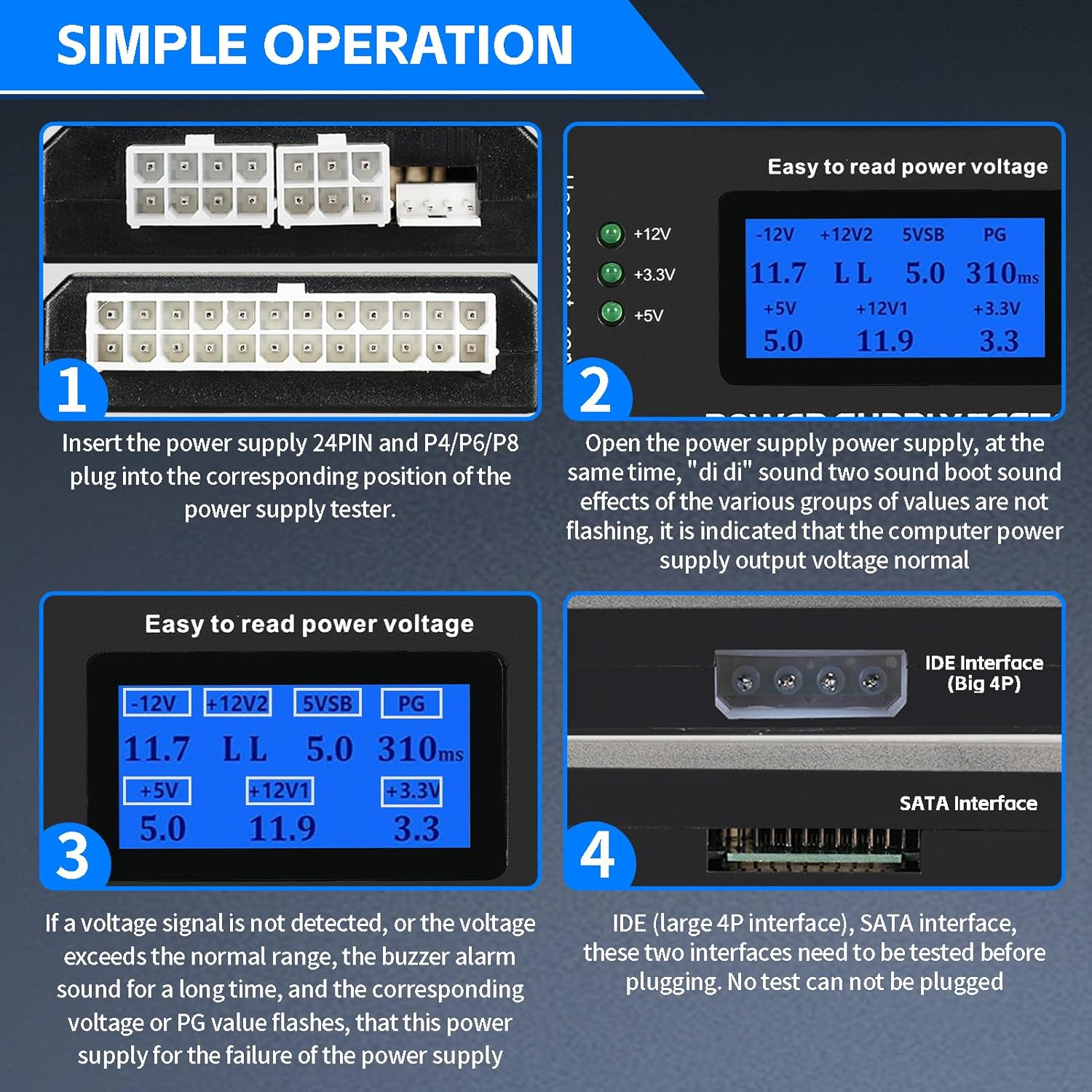
Image: Visual guide demonstrating the connection process for the power supply tester and initial display interpretation.
4. Operating Instructions
Once the power supply is connected to the tester, you can begin the testing process:
- After connecting the PSU to the tester, power on the PSU. The tester will automatically activate.
- Observe the LCD display. It will show real-time voltage readings for +12V, -12V, +5V, -5V, +3.3V, 5VSB (Standby Voltage), and PG (Power Good signal).
- The green indicator lights (+12V, +3.3V, +5V) on the side of the tester will illuminate if these voltages are present and within acceptable limits.
- Listen for any audible alarms. If the tester detects voltage parameters outside the normal range, a buzzer will sound, and the abnormal parameters on the LCD screen will flash. This indicates a potential issue with the power supply.
- Refer to the ATX Power Supply voltage requirements table below for standard voltage ranges.
ATX Power Supply Voltage Requirements

Image: A table outlining the acceptable voltage ranges for various ATX power supply outputs.
For a visual demonstration of the product's operation, please watch the video below:
Video: A short demonstration of the ASHATA LCD Power Supply Tester, showcasing its physical appearance and how it connects to a power supply.
5. Maintenance
To ensure the longevity and accurate performance of your ASHATA LCD Power Supply Tester, follow these simple maintenance guidelines:
- Cleaning: Use a soft, dry cloth to wipe the exterior of the tester. Avoid using abrasive cleaners or solvents, as they may damage the plastic casing or LCD screen.
- Storage: Store the tester in a cool, dry place away from direct sunlight and extreme temperatures. Keep it in its original packaging or a protective case when not in use to prevent dust accumulation and physical damage.
- Handling: Handle the tester with care. Avoid dropping it or subjecting it to strong impacts, which could damage internal components or the LCD display.
- Connector Care: Ensure that the connectors on the tester are free from dust and debris. Periodically inspect them for any signs of wear or damage.
6. Troubleshooting
If you encounter issues while using your ASHATA LCD Power Supply Tester, refer to the following common troubleshooting steps:
| Problem | Possible Cause | Solution |
|---|---|---|
| LCD Screen is Blank | Power supply not connected or not powered on. Faulty power supply. | Ensure the 20/24-pin ATX connector is fully inserted and the PSU is powered on. Test with a known good power supply if available. |
| Buzzer Alarm Sounds / Flashing Readings | Voltage readings are outside acceptable ATX specifications. | This indicates a potential fault with the power supply. Refer to the "ATX Power Supply Voltage Requirements" table in Section 4. Consider replacing the power supply if readings are consistently out of range. |
| Incorrect Readings | Loose connection. Tester malfunction. | Ensure all connectors are securely seated. If the issue persists, contact customer support. |
| Green LEDs Not Lighting Up | Missing or out-of-spec voltage on the corresponding rail. | Check the LCD display for specific voltage readings. If a voltage is too low or absent, the PSU may be faulty. |

Image: The tester highlighting its automatic alarm feature for detected defects.
7. Specifications
- Brand: ASHATA
- Model: LCD Power Supply Tester
- Power Source: Corded Electric (powered by PSU under test)
- Color: Black (default)
- Item Weight: 2.82 ounces (approx. 0.08 Kilograms)
- Product Dimensions (L x W x H): 3.94 x 1.97 x 0.79 inches
- Min. Operating Voltage: 0.01 Volts
- Measurement Type: Multimeter (integrated)
- Supported Interfaces: 20/24-pin ATX, SATA, 4-pin/8-pin CPU, 6-pin/8-pin PCIe, Molex (Big 4P), Floppy Drive
- Display: LCD Screen
- Safety Certification: CE
- UPC: 717207350523
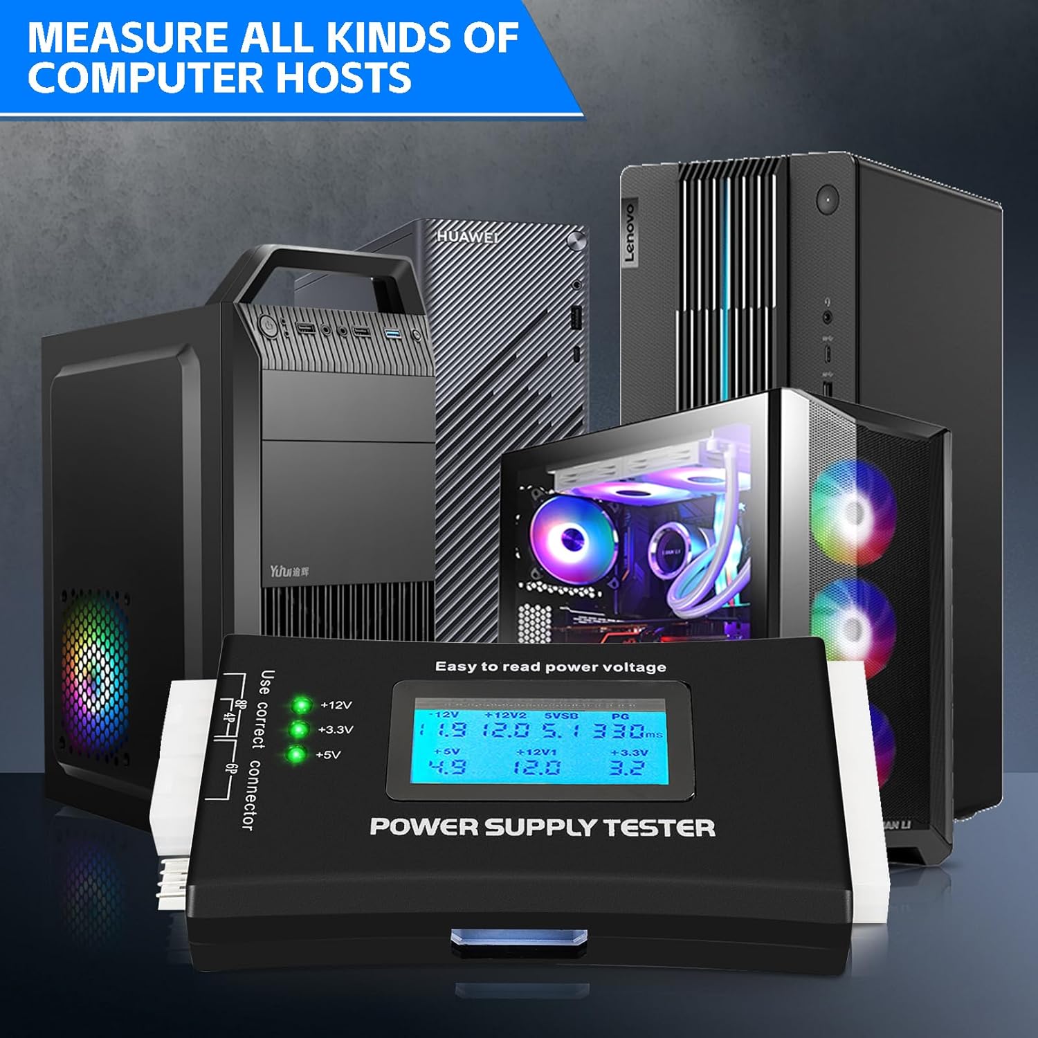
Image: The power supply tester demonstrating its ability to measure all kinds of computer hosts.

Image: An overview of all supported interfaces on the power supply tester.
8. Warranty and Support
ASHATA products are manufactured to high-quality standards. For specific warranty information and customer support, please refer to the documentation included with your purchase or visit the official ASHATA website. If you experience any issues not covered in this manual, please contact ASHATA customer service for assistance.
You can visit the ASHATA Store for more information: ASHATA Store on Amazon
Ask a question about this manual
Ask about setup, troubleshooting, compatibility, parts, safety, or missing instructions. Manuals+ will review the question and use this page’s manual context to help answer it.