1. Introduction
This manual provides detailed instructions for the safe and effective use of the Walfront PCB Circuit Board Solder Mask Repair Kit. This kit is designed for repairing printed circuit board (PCB) layer peeling or localized damage on computer and mobile phone PCBs. Please read this manual thoroughly before use to ensure proper application and optimal results.

Image 1.1: Walfront PCB Circuit Board Solder Mask Repair Kit components.
2. Safety Information
Always observe the following safety precautions when using this product:
- Wear appropriate personal protective equipment, such as gloves and safety glasses, to prevent skin and eye contact with the solder mask ink.
- Use in a well-ventilated area to avoid inhaling fumes.
- Keep out of reach of children and pets.
- Do not ingest the solder mask ink. If ingested, seek immediate medical attention.
- Store the solder mask ink in a cool, dark place, away from direct sunlight and heat sources.
- Dispose of used materials and empty containers according to local regulations.
3. Kit Components
The Walfront PCB Circuit Board Solder Mask Repair Kit includes the following items:
- UV Solder Mask Ink (Green Oil): A specialized ink designed to repair damaged PCB traces and protect components.
- Flashlight: A compact flashlight provided for general illumination during repair tasks.

Image 3.1: UV Solder Mask Ink (Green Oil).
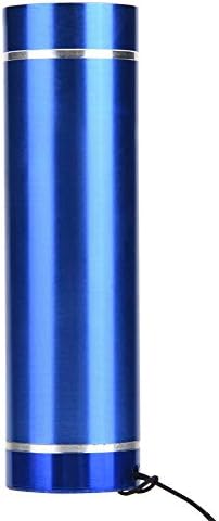
Image 3.2: Included Flashlight.
Note on Product Variants: The appearance of the solder mask ink tube may vary between new and old production models. Both types contain the same functional product.

Image 3.3: New and Old Solder Mask Ink Tube Models.
4. Setup
Before beginning any repair, ensure your workspace is clean, well-lit, and well-ventilated. Gather all necessary tools, including:
- The Walfront PCB Circuit Board Solder Mask Repair Kit.
- Isopropyl alcohol (IPA) or a suitable PCB cleaner.
- Cotton swabs or lint-free cloths.
- Precision tools (e.g., tweezers, fine-tip applicators) for detailed work.
- A dedicated UV light source (essential for curing the solder mask ink, as detailed in the Troubleshooting section).
5. Operating Instructions
Follow these steps to repair damaged PCB areas using the solder mask kit:
- Prepare the Damaged Area:
- Carefully clean the damaged PCB area with isopropyl alcohol and a lint-free cloth or cotton swab. Ensure all dirt, grease, and oxidation are removed.
- Allow the area to dry completely before proceeding.
- Apply Solder Mask Ink:
- Dispense a small amount of the green UV solder mask ink onto the damaged area. Use a fine-tip applicator or toothpick to spread the ink evenly over the exposed traces or damaged sections.
- Ensure the ink covers the entire repair area, creating a thin, uniform layer. Avoid applying excessive amounts.
- If using stencils, it is recommended to coat the stencils with flux to prevent the solder mask ink from sticking.

Image 5.1: Applying solder mask ink to a PCB.
- Cure the Solder Mask Ink:
- The green solder mask ink is a UV-curable product. It requires exposure to ultraviolet (UV) light to harden and form a protective layer.
- Position a dedicated UV light source approximately 1-2 cm above the applied solder mask.
- Expose the ink to UV light for approximately 5-10 minutes, or until it is completely hardened. Curing time may vary depending on the intensity of your UV light source and the thickness of the applied ink.
- After curing, the solder mask should be firm and non-tacky to the touch.
- Inspect the Repair:
- Visually inspect the repaired area to ensure the solder mask has fully cured and provides adequate protection.
- If necessary, apply additional layers and cure them individually until the desired thickness and protection are achieved.
6. Maintenance
Proper storage and care will extend the life of your solder mask kit:
- Solder Mask Ink: After each use, securely cap the solder mask ink tube to prevent air exposure and premature hardening. Store in a cool, dark place, ideally refrigerated, to maintain its viscosity and shelf life. Avoid exposure to any light, especially UV light, during storage.
- Flashlight: The flashlight requires 3 AAA batteries (not included). Replace batteries as needed. Keep the flashlight clean and dry.
7. Troubleshooting
| Problem | Possible Cause | Solution |
|---|---|---|
| Solder mask ink does not cure or remains tacky. | Insufficient UV light exposure or incorrect light source. The flashlight included in this kit emits white light, not UV light. | The flashlight provided in this kit is a standard white light source and is NOT suitable for curing UV solder mask ink. A separate, dedicated UV light source (e.g., a UV LED lamp or UV flashlight with a wavelength of 365nm-405nm) is required to properly cure the solder mask. Ensure adequate exposure time (5-10 minutes) and proximity to the UV light source. |
| Solder mask ink sticks to stencils. | Lack of a release agent on the stencil surface. | Apply a thin layer of flux to the stencil before applying the solder mask ink. This helps prevent adhesion. |
| Solder mask ink is too thick or uneven. | Excessive application or improper spreading. | Apply the ink in thin, even layers. Use a fine-tip applicator for precision. Multiple thin layers are better than one thick layer. |

Image 7.1: The included flashlight emits white light, not UV light.
8. Specifications
- Brand: Walfront
- Model Number: Wal frontfmrza58xnk-03
- Item Weight: 3.52 ounces (approx. 100g)
- Product Dimensions: 4.72 x 3.94 x 0.79 inches (approx. 12 x 10 x 2 cm)
- Material: Plastic (for components)
- Solder Mask Type: UV Curing Solder Mask Ink (Green)
- Flashlight Power Source: Batteries (3x AAA, not included)
- ASIN: B07WFS6NBH
- Date First Available: August 15, 2019
9. Warranty Information
This product is covered by a standard manufacturer's warranty against defects in materials and workmanship. For specific warranty terms and conditions, please refer to the product packaging or contact Walfront customer support. The warranty does not cover damage resulting from misuse, improper application, or failure to follow instructions in this manual.
10. Customer Support
For technical assistance, product inquiries, or support, please contact Walfront customer service through the retailer where the product was purchased or visit the official Walfront website. Please have your product model number (Wal frontfmrza58xnk-03) and purchase details ready when contacting support.


