
1. Product Overview
The Cambium Networks PMP 450b High Gain 5 GHz Radio is designed to enhance wireless network performance. This device functions as a Subscriber Module (SM) and features ultra-wide band radios, supporting frequencies from 4.9 to 5.925 GHz. It includes a Gigabit Ethernet Interface for high data transfer rates and a 3.5 mm audio jack for direct headphone connection. The integrated System on a Chip (SoC) significantly boosts packet processing power, enabling aggregate speeds of up to 300 Mbps in a 40 MHz channel.
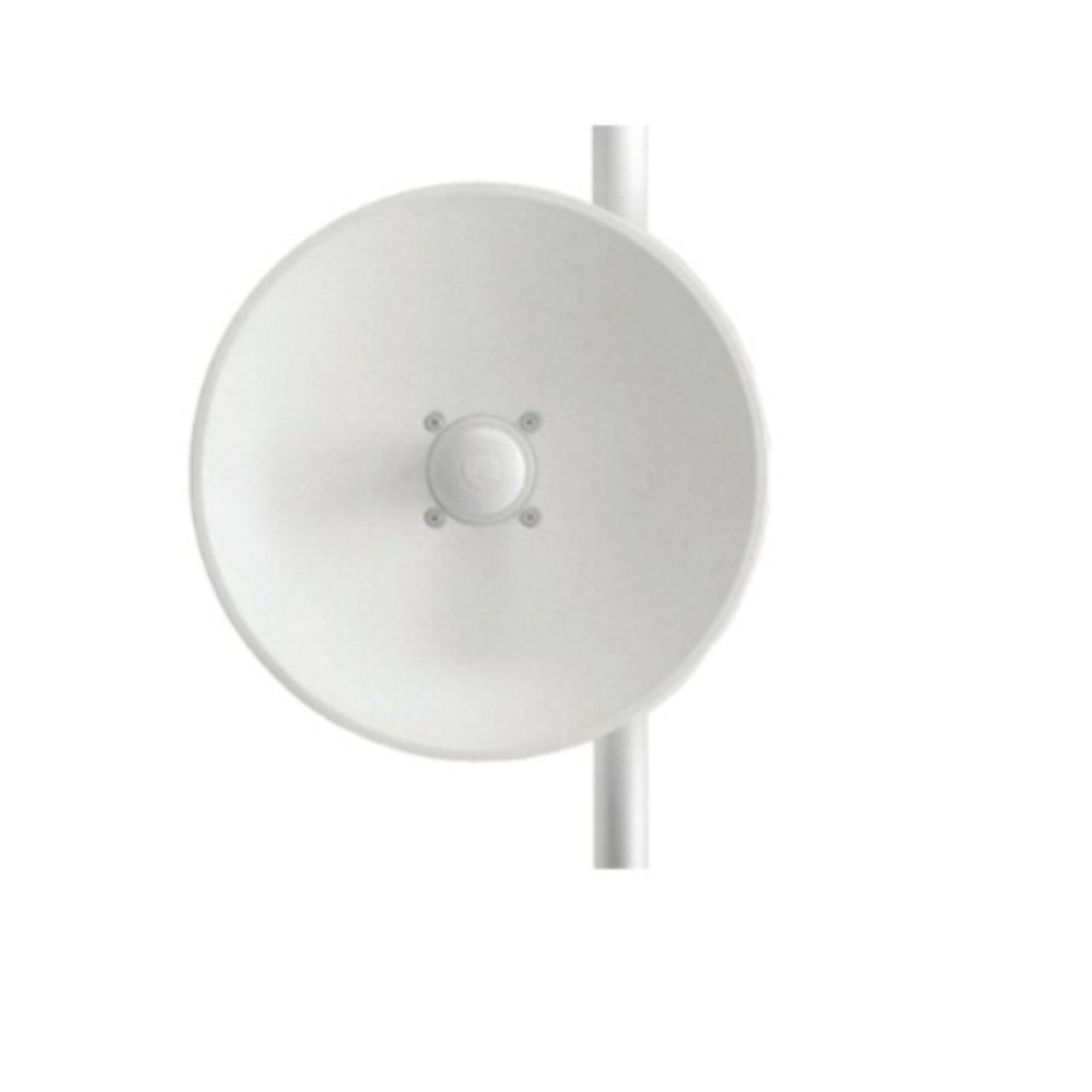
Figure 1: Cambium Networks PMP 450b High Gain 5 GHz Radio (Radio Only)
This image displays the Cambium Networks PMP 450b High Gain 5 GHz Radio unit. It is a compact, rectangular device, typically used in outdoor wireless networking applications. The unit features connectors for power and data, and an integrated antenna for signal transmission and reception.
This manual provides essential information for the proper installation, operation, and maintenance of your PMP 450b High Gain Radio.
2. Package Contents
Verify that your package contains the following items:
- Cambium Networks PMP 450b High Gain 5 GHz Radio Unit (Radio Only)
- Quick Start Guide (if applicable, not included in this "Radio Only" package)
- Mounting hardware (sold separately or not included in "Radio Only" package)
- Power supply unit (sold separately or not included in "Radio Only" package)
If any items are missing or damaged, please contact your vendor or Cambium Networks support.
3. Setup and Installation
The PMP 450b High Gain Radio is designed for professional installation. Ensure all local regulations and safety guidelines are followed during installation.
3.1. Site Selection
Choose a mounting location that provides a clear line of sight to the Access Point (AP) and minimizes potential interference. Consider factors such as elevation, proximity to power sources, and structural stability.
3.2. Mounting the Radio
Mount the radio securely using appropriate mounting hardware (not included with the "Radio Only" unit). Ensure the radio is oriented correctly for optimal signal alignment with the Access Point.
3.3. Cabling
- Connect a standard Ethernet cable (Cat5e or higher) from your network device (e.g., PoE injector, switch) to the Gigabit Ethernet port on the PMP 450b radio.
- Ensure proper grounding of the unit and cabling to protect against lightning and static discharge.
3.4. Initial Power-Up
Once mounted and cabled, apply power to the unit via a compatible Power over Ethernet (PoE) injector or switch. Observe the LED indicators for power and link status.
4. Operating Instructions
After successful physical installation and power-up, the PMP 450b radio requires configuration via its web interface.
4.1. Accessing the Web Interface
- Connect a computer directly to the PoE injector's data port or to the network segment where the radio is connected.
- Configure your computer's network adapter to be on the same subnet as the radio's default IP address (refer to product documentation for default IP).
- Open a web browser and enter the radio's IP address.
- Log in using the default username and password (refer to product documentation).
4.2. Basic Configuration
Within the web interface, configure the following essential settings:
- Network Settings: Assign a static IP address, subnet mask, and gateway.
- Wireless Settings: Configure the operating frequency, channel width, and connect to the desired Access Point (AP). Ensure the security settings (e.g., WPA2) match the AP.
- System Settings: Change default login credentials, set time and date, and update firmware if necessary.
4.3. Monitoring Performance
The web interface provides tools to monitor the radio's performance, including signal strength, data rates, and error statistics. Regularly check these metrics to ensure optimal operation.
5. Maintenance
Regular maintenance ensures the longevity and reliable performance of your PMP 450b High Gain Radio.
5.1. Firmware Updates
Periodically check the Cambium Networks website for new firmware versions. Updating firmware can provide performance improvements, new features, and security enhancements. Follow the provided instructions carefully during the update process.
5.2. Physical Inspection
Conduct periodic visual inspections of the radio and its cabling. Check for:
- Loose connections
- Cable damage
- Corrosion on connectors
- Physical damage to the unit or mounting hardware
5.3. Cleaning
If necessary, gently clean the exterior of the unit with a soft, damp cloth. Do not use harsh chemicals or abrasive materials. Ensure all ports are free from dust and debris.
6. Troubleshooting
This section provides solutions to common issues you might encounter.
6.1. No Power
- Check Power Source: Ensure the PoE injector or switch is receiving power and is functioning correctly.
- Check Ethernet Cable: Verify the Ethernet cable connecting the radio to the PoE source is securely connected and undamaged.
- Verify PoE Compatibility: Ensure the PoE source provides the correct voltage and power for the PMP 450b.
6.2. No Network Connectivity
- Check Link Status: Observe the LED indicators on the radio and the connected network device. A solid link LED indicates a physical connection.
- Verify Configuration: Ensure the radio's IP address, subnet mask, and gateway are correctly configured and compatible with your network.
- Wireless Link: Confirm the radio is successfully associated with the Access Point. Check signal strength and alignment.
- Firewall Settings: Ensure no firewall rules are blocking communication.
6.3. Poor Performance
- Signal Strength: Check the signal strength and quality in the web interface. Poor signal may require antenna realignment or a clearer line of sight.
- Interference: Identify and mitigate sources of interference (e.g., other wireless devices, environmental factors).
- Channel Width: Ensure the channel width is appropriate for your environment and desired throughput.
- Firmware: Ensure the latest firmware is installed.
7. Specifications
| Feature | Detail |
|---|---|
| Brand | Cambium Networks |
| Model Number | C050045B022A |
| Frequency Range | 4900-5925 MHz |
| Channel Width | 5 MHz, 10 MHz, 15 MHz, 20 MHz, 30 MHz, or 40 MHz |
| Ethernet Interface | 100/1000BaseT, full duplex, auto negotiated |
| Physical Layer | 2x2 MIMO OFDM |
| Encryption | FIPS-197 128-bit AES, 256-bit AES (optional) |
| Maximum Deployment Range | Up to 40 miles (64 km) |
| Latency | 3-5ms, typical |
| GPS Synchronization | Yes, synchronized by Access Point |
| Maximum Transit Power | +27 dBm (MIMO, combined V+H) (+22 dBm @ 256QAM) |
| Integrated Antenna Peak Gain | 24 dBi |
| Item Weight | 0.25 Pounds |
| UPC | 646444466592 |
8. Warranty Information
According to product specifications, this item comes with No Warranty. Please refer to your purchase agreement or contact your vendor for any specific return or exchange policies.
9. Support and Contact
For technical assistance, further documentation, or to report issues, please visit the official Cambium Networks support website or contact their customer service.
- Cambium Networks Website: www.cambiumnetworks.com
- Support Portal: Refer to the Cambium Networks website for their dedicated support portal and contact information.
When contacting support, please have your product model number (C050045B022A) and any relevant error messages or diagnostic information ready.


