
1. Introduction
This manual provides detailed instructions for the Taidacent 12V 3A High Power Long Distance Wireless Inductive Coil Modules. This module set is designed for wireless power transmission, featuring a transmitter and a receiver coil, capable of delivering 12V at 3A. Please read this manual thoroughly before installation and operation to ensure proper use and safety.
2. Safety Information
- Operating Distance: Maintain a transmission distance greater than 5mm between the transmitter and receiver coils. Operating at distances less than 5mm can lead to excessively high receiving voltage, potentially damaging the module.
- Heat Generation: The modules may generate heat during operation. Ensure adequate ventilation and avoid enclosing the modules in confined spaces without proper heat dissipation.
- Power Supply: Use a stable 24V DC power supply for the transmitter module. Incorrect input voltage can damage the device.
- Polarity: Always observe correct polarity when connecting the power supply and output load. Incorrect connections can cause damage.
- Environmental Conditions: Avoid exposing the modules to moisture, dust, or extreme temperatures.
- Professional Installation: If you are unfamiliar with electronic circuits, seek professional assistance for installation.
3. Package Contents
Verify that all items are present in your package:
- 1 x Wireless Transmitter Module with Coil
- 1 x Wireless Receiver Module with Coil
4. Product Overview
The Taidacent wireless power supply module consists of two main components: a transmitting module and a receiving module, each with an inductive coil. The transmitting module converts the input DC power into a high-frequency alternating magnetic field, which is then picked up by the receiving coil and converted back into DC power for your load.

Figure 4.1: Overview of the Wireless Inductive Coil Modules setup.

Figure 4.2: Components of the Taidacent 12V 3A Wireless Power Module.
Transmitter Module
The transmitter module is responsible for generating the magnetic field. It includes a power input and connects to the transmitting coil.

Figure 4.3: Transmitting Module with Heatsink.
Receiver Module
The receiver module captures the magnetic field and converts it into usable DC power. It provides the 12V 3A output for your connected devices.
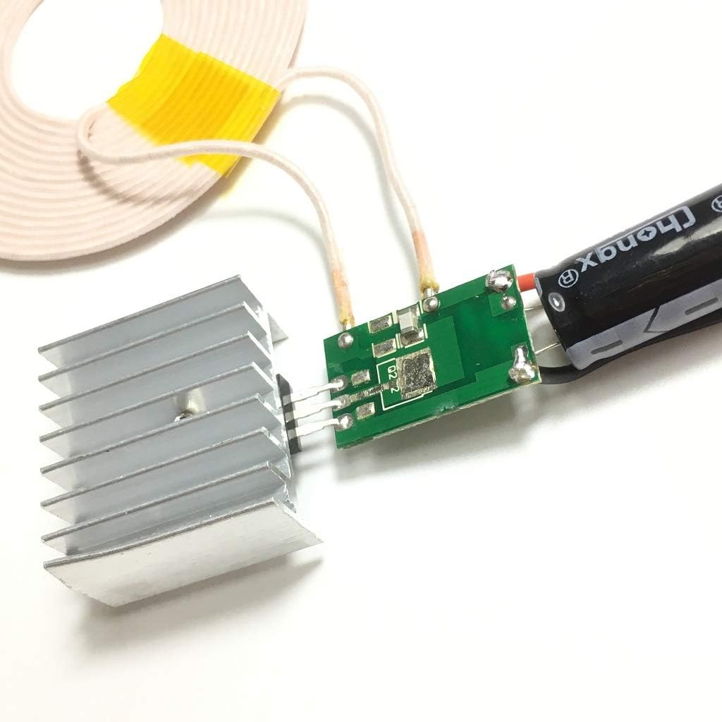
Figure 4.4: Receiving Module.
5. Setup Instructions
- Connect Transmitter Coil: Connect the transmitting coil to the designated terminals on the transmitter module. Ensure a secure connection.
- Connect Receiver Coil: Connect the receiving coil to the designated terminals on the receiver module.
- Power the Transmitter: Connect a 24V DC power supply to the input terminals of the transmitter module. Observe correct polarity (+ to + and - to -).
- Connect Load to Receiver: Connect your 12V device or load to the output terminals of the receiver module. Ensure correct polarity.
- Position Coils: Place the transmitting and receiving coils facing each other. Ensure the distance between the coils is greater than 5mm but within the effective transmission range (refer to specifications for optimal range).
- Power On: Once all connections are secure and coils are positioned, apply power to the 24V DC input. The receiver module should now output 12V 3A to your connected load.
Important: Do not allow the coils to touch or be closer than 5mm during operation, as this can cause overvoltage and damage the receiver module.
6. Operating Instructions
Once the modules are set up as described in Section 5, operation is straightforward:
- Power Activation: Apply 24V DC power to the transmitter module. The system will automatically begin wireless power transmission.
- Coil Alignment: For optimal performance, ensure the transmitting and receiving coils are aligned concentrically.
- Transmission Distance: The module is designed for long-distance wireless power transfer. Refer to the specifications for the effective range and corresponding output power. Note that output power decreases as the distance between coils increases.
- Monitoring: If possible, monitor the output voltage and current to ensure it meets the requirements of your connected load and remains within safe operating parameters.
7. Maintenance
These wireless inductive coil modules require minimal maintenance. Follow these guidelines to ensure longevity:
- Cleaning: Keep the modules and coils clean and free from dust and debris. Use a soft, dry cloth for cleaning. Do not use liquid cleaners.
- Environmental Protection: Protect the modules from moisture, corrosive substances, and extreme temperatures.
- Inspection: Periodically inspect all connections for looseness or damage. Ensure the heatsink on the transmitter module is clear of obstructions for proper cooling.
- Storage: When not in use for extended periods, store the modules in a dry, cool environment.
8. Troubleshooting
| Problem | Possible Cause | Solution |
|---|---|---|
| No power output from receiver. |
|
|
| Receiver module gets excessively hot. |
|
|
| Output voltage is lower than expected. |
|
|
9. Specifications
| Feature | Detail |
|---|---|
| Model Number | TD-801-901-12 |
| Input Voltage | 24 Volts DC |
| Output Voltage | 12 Volts DC |
| Output Current | 3 Amps |
| Output Power | 36 Watts |
| Transmitter Module Size | 17mm x 30mm |
| Receiver Module Size | 30mm x 54mm |
| Coil Size | Outer diameter 82mm, Inner diameter 30mm |
| Minimum Operating Distance | > 5mm (to prevent damage) |
| Material | Plastic (Enclosure) |
| Included Components | 1 x Transmitter Module with Coil, 1 x Receiver Module with Coil |
Output Power vs. Distance
- Output voltage 12V 2.6A at 14mm
- Output voltage 12V 2.5A at 15mm
- Output voltage 12V 2.3A at 16mm
- Output voltage 12V 2A at 17mm
- Output voltage 12V 1.8A at 18mm
- Output voltage 12V 1.8A at 19mm
- Output voltage 12V 1.6A at 20mm
- Output voltage 12V 1.5A at 21mm
- Output voltage 12V 1.5A at 22mm
- Output voltage 12V 1.4A at 23mm
- Output voltage 12V 1.2A at 24mm
- Output voltage 12V 1.1A at 25mm
10. Warranty Information
Warranty details for the Taidacent 12V 3A High Power Long Distance Wireless Inductive Coil Modules are not provided in this manual. Please refer to the product packaging, the seller's website, or contact the manufacturer directly for specific warranty terms and conditions.
11. Support
For technical assistance, troubleshooting beyond this manual, or inquiries regarding your Taidacent product, please contact your point of purchase or the manufacturer directly. Ensure you have your model number (TD-801-901-12) and purchase information available when seeking support.