1. Introduction
Welcome to the FIMER QUEEN 180 Inverter Welding Machine user manual. This document provides essential information for the safe and efficient operation, setup, and maintenance of your welding equipment.
The FIMER QUEEN 180 is a versatile inverter welding machine designed for MIG/MAG and MMA welding processes, offering a wide range of applications from light carpentry to automotive and agricultural sectors. Manufactured in Italy, it combines robust design with advanced technology.
2. Important Safety Information
Welding can be dangerous. Always follow safety precautions to prevent injury or damage to property. Failure to comply with these instructions may result in serious injury or death.
- Read and understand this manual completely before operating the machine.
- Wear appropriate personal protective equipment (PPE), including a welding helmet with proper shade, flame-resistant gloves, and protective clothing.
- Ensure adequate ventilation in the work area to avoid inhaling welding fumes, which can be hazardous to health.
- Protect bystanders from arc rays, sparks, and hot metal by using welding screens or ensuring they maintain a safe distance.
- Disconnect the power supply to the machine before performing any maintenance, adjustments, or changing consumables.
- Do not operate the welding machine in damp or wet conditions, or in areas with explosive atmospheres.
- Ensure proper grounding of the equipment and the workpiece to prevent electric shock.
- Always use the correct voltage and fuse rating as specified in the technical specifications.
3. Product Overview
The FIMER QUEEN 180 is a compact and powerful inverter welding machine designed for versatility and ease of use.

Figure 1: Front view of the FIMER QUEEN 180 Inverter Welding Machine. This image shows the control panel with its knobs and display, as well as the welding torch connection points and output terminals.
Key Features:
- MIG-MAG 180A welding machine with internal spool holder (max. 5 kg).
- Manufactured in Italy, ensuring quality and reliability.
- Adjustable welding current range: 20-180A.
- Operates on a standard 230V power supply.
- Supports welding wire diameters from 0.6 mm to 1.0 mm.
4. Setup and Installation
4.1 Unpacking
Carefully remove the welding machine and all included accessories from the packaging. Inspect all components for any signs of damage during transit. Report any damage to your supplier immediately.
4.2 Power Connection
- Connect the machine to a 230V, single-phase power supply.
- Ensure the power outlet is properly grounded and can handle the required current. Refer to the technical specifications for maximum power consumption.
- The machine requires a 16A delayed-action fuse for optimal protection.
4.3 Welding Wire Installation (MIG/MAG)
The FIMER QUEEN 180 features an internal spool holder designed for welding wire spools up to 5 kg.
- Open the side panel of the machine to access the wire spool compartment.
- Mount the wire spool onto the holder, ensuring the wire unwinds smoothly from the bottom.
- Thread the welding wire through the wire feeder mechanism, ensuring it passes through the correct groove on the feed roller.
- Select the appropriate wire feed roller for your specific wire diameter (0.6 mm to 1.0 mm).
- Close the side panel securely.
4.4 Gas Connection (MIG/MAG)
For MIG/MAG welding, connect the gas hose from your shielding gas cylinder (e.g., Argon, CO2, or mixed gas) to the gas inlet connector located on the rear of the machine. Ensure all connections are secure and leak-free to prevent gas wastage and ensure proper shielding.
4.5 Torch and Ground Clamp Connection
- MIG/MAG Welding: Connect the MIG torch to the Euro connector on the front panel of the machine. Connect the ground clamp cable to the negative (-) terminal and securely attach the clamp to the workpiece, ensuring good electrical contact.
- MMA (Stick) Welding: Connect the electrode holder cable to the positive (+) terminal and the ground clamp cable to the negative (-) terminal. Secure the ground clamp to the workpiece.
5. Operating Instructions
5.1 Control Panel Overview
The FIMER QUEEN 180's control panel allows for precise adjustment of welding parameters.

Figure 2: FIMER QUEEN 180 with key features highlighted. The control panel is visible on the left, showing adjustment knobs and digital display.
5.2 MIG/MAG Welding Procedure
- Power On: Turn on the main power switch located on the rear of the machine.
- Select Mode: Choose MIG/MAG welding mode on the control panel.
- Adjust Parameters: Set the welding current (Amperage) and wire feed speed according to the material thickness, wire diameter, and desired weld characteristics. Consult a welding chart for recommended settings.
- Gas Flow: Open the valve on your gas cylinder and adjust the gas flow rate using the regulator.
- Ground Connection: Ensure the ground clamp is securely attached to the workpiece, providing good electrical contact.
- Welding: Hold the MIG torch at the correct angle and distance from the workpiece. Press the torch trigger to initiate the arc and begin welding. Maintain a consistent travel speed and arc length.
5.3 MMA (Stick) Welding Procedure
- Power On: Turn on the main power switch.
- Select Mode: Choose MMA welding mode on the control panel.
- Connect Cables: Ensure the electrode holder is connected to the positive (+) terminal and the ground clamp to the negative (-) terminal.
- Insert Electrode: Insert the appropriate electrode into the electrode holder.
- Adjust Current: Set the welding current based on the electrode type and diameter.
- Ground Connection: Secure the ground clamp to the workpiece.
- Welding: Strike the arc by lightly touching and then quickly lifting the electrode from the workpiece. Maintain a consistent arc length and travel speed to achieve a stable weld.
6. Maintenance and Care
Regular maintenance ensures the longevity, optimal performance, and safety of your FIMER QUEEN 180 welding machine.
- Cleaning: Periodically clean the machine's exterior with a dry, soft cloth. Ensure cooling vents are free from dust, metal particles, and debris to prevent overheating. Use compressed air to gently blow out internal dust if necessary, ensuring the machine is unplugged.
- Wire Feeder: Inspect the wire feed rollers and guides for wear or damage. Clean any accumulated dust or metal particles from the wire feed mechanism. Replace worn rollers to ensure consistent wire feeding.
- MIG Torch: Regularly check the MIG torch nozzle, contact tip, and gas diffuser for spatter buildup, wear, or damage. Clean spatter and replace worn consumables as needed to maintain proper gas shielding and arc stability.
- Cables: Inspect all welding cables (power, ground, torch) for cuts, fraying, or damaged insulation. Replace frayed or damaged cables immediately to prevent electrical hazards. Ensure connections are tight.
- Storage: When not in use, store the welding machine in a dry, clean, and well-ventilated environment, protected from dust and moisture.
7. Troubleshooting Guide
This section addresses common issues you might encounter during the operation of your FIMER QUEEN 180. For problems not listed here, contact customer support.
| Problem | Possible Cause | Solution |
|---|---|---|
| No power to the machine | Power cable disconnected, faulty power outlet, tripped circuit breaker/fuse | Check all power connections, test the power outlet, reset the circuit breaker or replace the fuse. |
| No welding arc | Poor ground connection, incorrect welding settings, faulty electrode/wire, torch trigger not pressed (MIG) | Ensure a good, clean ground connection. Adjust welding current/voltage. Check electrode/wire for damage. Press torch trigger fully. |
| Poor weld quality (e.g., porosity, lack of fusion) | Incorrect welding parameters, improper technique, contaminated base material, insufficient gas shielding (MIG) | Adjust current, voltage, and wire speed. Review welding technique. Clean workpiece thoroughly. Check gas flow and connections (MIG). |
| Wire feeding issues (MIG) | Kinked or tangled wire, incorrect wire feed roller size, clogged torch liner, worn contact tip | Check wire path for obstructions. Ensure correct roller size for wire diameter. Clean or replace torch liner. Replace worn contact tip. |
| Overheating / Thermal overload | Exceeding duty cycle, blocked cooling vents, high ambient temperature | Allow the machine to cool down. Ensure cooling vents are clear. Reduce welding time or current. |
8. Technical Specifications
The following table provides detailed technical specifications for the FIMER QUEEN 180 welding machine.
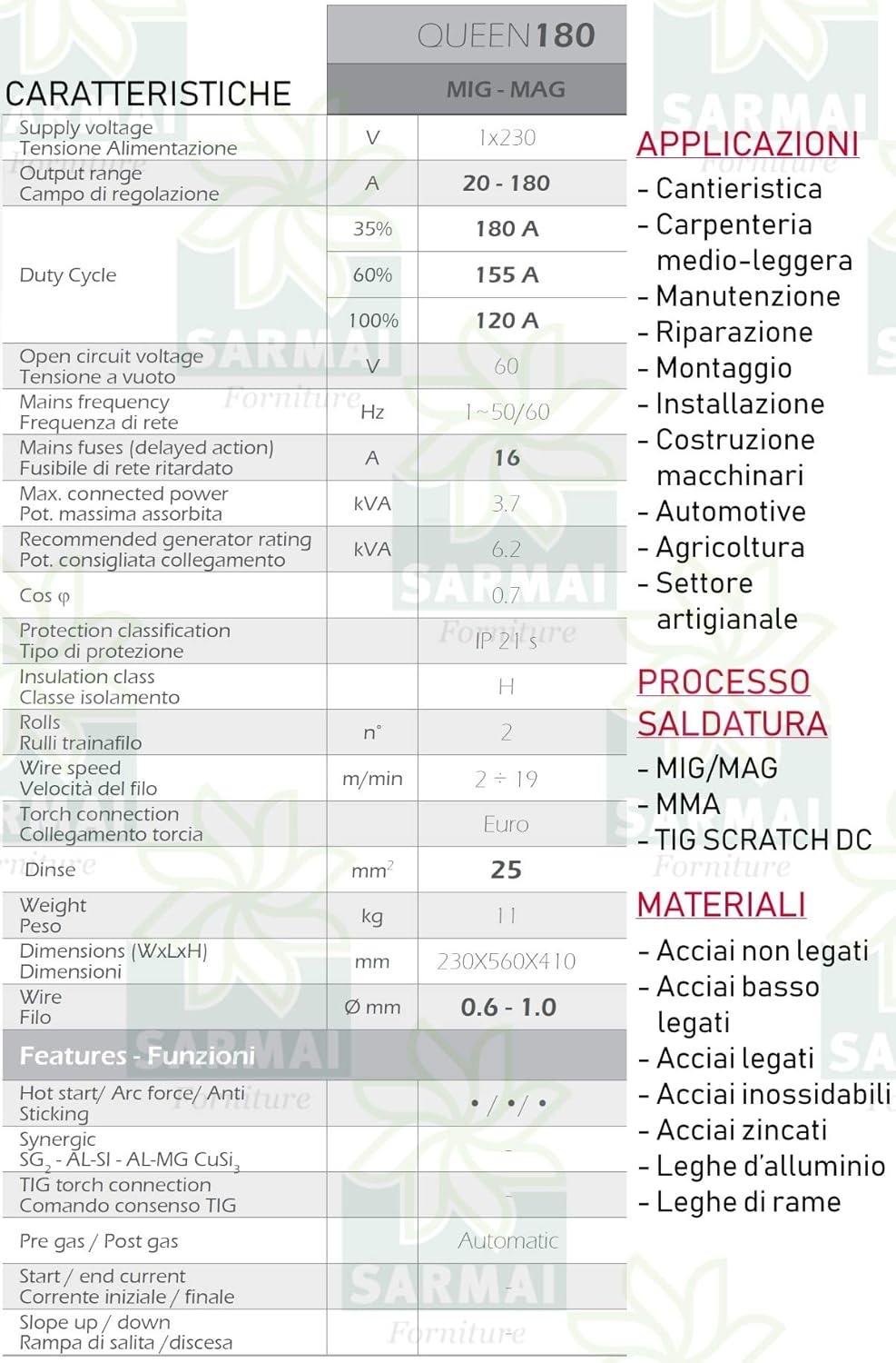
Figure 3: Detailed technical specifications table for the FIMER QUEEN 180.
| Feature | Value |
|---|---|
| Supply Voltage | 1x230 V |
| Output Range | 20 - 180 A |
| Duty Cycle (35%) | 180 A |
| Duty Cycle (60%) | 155 A |
| Duty Cycle (100%) | 120 A |
| Open Circuit Voltage | 60 V |
| Mains Frequency | 1~50/60 Hz |
| Mains Fuse (delayed action) | 16 A |
| Max. Connected Power | 3.7 kVA |
| Recommended Generator Rating | 6.2 kVA |
| Protection Classification | IP 21 S |
| Insulation Class | H |
| Wire Feed Rolls | 2 |
| Wire Speed | 2 - 19 m/min |
| Torch Connection | Euro |
| Weight | 11 kg |
| Dimensions (WxLxH) | 230x560x410 mm |
| Wire Diameter | 0.6 - 1.0 mm |
| Hot Start / Arc Force / Anti Sticking | Yes |
| Pre gas / Post gas | Automatic |
| Start / End current | Yes |
| Slope up / down | Yes |
9. Warranty and Customer Support
For warranty information, technical assistance, or spare parts, please contact FIMER customer support or your authorized FIMER dealer. It is recommended to keep your purchase receipt as proof of purchase for warranty claims.
Note: Information regarding guaranteed software updates for this product is currently unknown.


