1. Introduction
This manual provides essential information for the safe and efficient operation of the Vikye SKI780-5D5G-4 5.5kW 380V 3-Phase VFD Frequency Converter. This device is designed for universal motor control applications, offering precise speed and torque regulation for various industrial processes. Please read this manual thoroughly before installation, operation, or maintenance to ensure proper usage and prevent potential hazards.
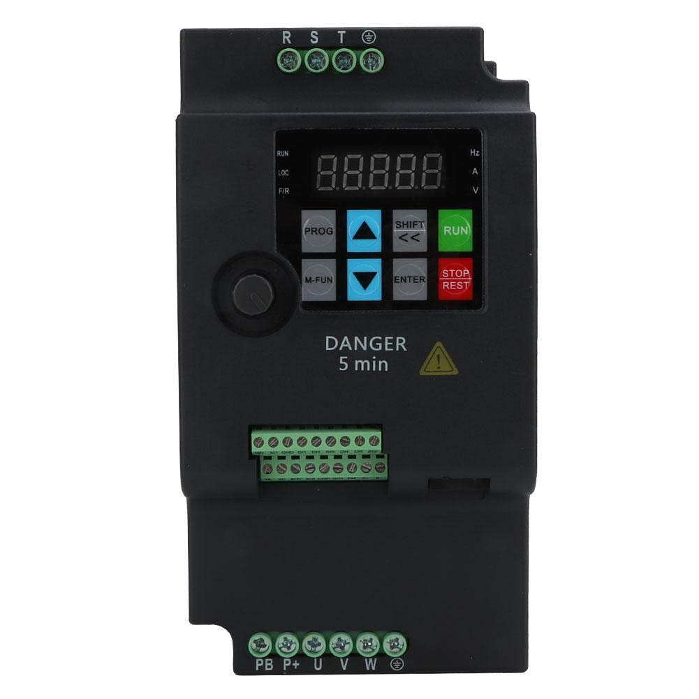
Figure 1: Vikye SKI780-5D5G-4 Frequency Converter in an industrial application.
2. Safety Information
WARNING: Improper installation or operation can lead to serious injury or death. Only qualified personnel should install, operate, and maintain this equipment. Always disconnect power before performing any work on the VFD or connected motor.
- Electrical Hazard: This device operates with high voltage (380V AC). Ensure all power is disconnected and verified before touching any terminals.
- Discharge Time: Capacitors inside the VFD can retain dangerous voltage even after power is disconnected. Wait at least 5 minutes after disconnecting power before touching any internal components or terminals. A "DANGER 5 min" label is present on the unit.
- Grounding: Ensure the VFD and the motor are properly grounded according to local electrical codes.
- Overcurrent Protection: Install appropriate overcurrent protection devices (fuses or circuit breakers) for the input power supply.
- Environmental Conditions: Do not operate the VFD in environments with excessive dust, moisture, corrosive gases, or flammable materials.
- Emergency Stop: Ensure an accessible emergency stop mechanism is in place for the entire system.
3. Product Features
The Vikye SKI780-5D5G-4 Frequency Converter offers a range of advanced features for precise and flexible motor control:
- Integrated Braking Unit: Features a built-in braking unit, requiring only an external braking resistor for rapid forward and reverse rotation switching.
- Wide Output Frequency Range: Supports a low-frequency mode from 0 to 500 Hz, suitable for various motor applications.
- Multi-Segment Operation: Provides 16-segment programmable multi-speed control, allowing for diverse operational modes.
- Communication Protocols: Offers multiple communication protocols for flexible integration and linkage synchronization control functions.
- PID Control: Widely applicable for constant pressure water supply, wind pressure constant pressure control, and similar systems requiring precise regulation.
- Current Vector Control: Utilizes current vector control method for enhanced motor performance and efficiency.
4. Specifications
Detailed technical specifications for the SKI780-5D5G-4 model are provided below:
| Parameter | Value |
|---|---|
| Model | SKI780-5D5G-4 |
| Application Range | Universal |
| Power Phase Number | Three-phase |
| Power Supply Voltage | Three-phase AC380V 50/60Hz |
| Output Voltage | Three-phase AC380V |
| Adapted Motor Power | 5.5 kW |
| DC Power Supply Characteristics | Voltage type |
| Control Method | Current Vector |
| Output Voltage Regulation Mode | PWM Control |
| Rated Current | 13 A |
| Product Dimensions (L x W x H) | Approx. 180 x 115 x 95 mm (7.1 x 4.5 x 3.7 inches) |
| Panel Opening Size | Approx. 61 x 82 mm (2.4 x 3.2 inches) |
| Weight | Approx. 1.5 kg |
| Frequency | 60 Hz (Input) |

Figure 2: Product dimensions of the SKI780-5D5G-4.
5. Setup and Installation
Before proceeding with installation, ensure all safety precautions are understood and followed. Installation should only be performed by qualified electricians.
5.1 Mounting
- Mount the VFD vertically on a flat, stable surface in an enclosure that provides adequate ventilation.
- Ensure sufficient clearance around the unit for airflow and heat dissipation.
- Avoid mounting near heat sources or in direct sunlight.
5.2 Wiring Connections
Refer to the wiring diagram provided with your unit for specific terminal connections. General connections include:
- Input Power (R, S, T): Connect the three-phase AC380V power supply to the R, S, T terminals. Ensure correct phase sequence.
- Ground (PE): Connect the protective earth ground to the PE terminal. This is critical for safety.
- Motor Output (U, V, W): Connect the three-phase motor leads to the U, V, W terminals.
- Braking Resistor (PB, P+): If an external braking resistor is used, connect it to the PB and P+ terminals. Consult the VFD's detailed manual for resistor sizing.
- Control Terminals (DI, DO, AI, AO, etc.): Connect control signals (e.g., start/stop, speed reference, fault outputs) to the designated control terminals as per your application requirements.

Figure 3: Top view of the VFD showing various connection terminals.

Figure 4: Rear label with model and serial number for identification. Serial Number: H05504050701003
6. Operating Instructions
The VFD features a control panel for parameter setting and operational control.

Figure 5: Front control panel of the VFD.
6.1 Control Panel Overview
- Display: Shows operational status, frequency, current, voltage, and parameter values.
- PROG Button: Enters/exits parameter programming mode.
- M-FUN Button: Accesses multi-function settings.
- SHIFT / UP / DOWN Buttons: Used for navigating parameters and adjusting values.
- ENTER Button: Confirms parameter settings.
- RUN Button: Starts the motor.
- STOP/RESET Button: Stops the motor or resets fault conditions.
6.2 Basic Operation
- Power On: Apply three-phase AC380V power to the VFD. The display will illuminate.
- Parameter Setting:
- Press PROG to enter parameter mode.
- Use UP/DOWN to select the desired parameter group and parameter number.
- Press ENTER to view or modify the parameter value.
- Use UP/DOWN to adjust the value.
- Press ENTER to save the new value.
- Press PROG to exit parameter mode.
- Motor Start: Press the RUN button. The motor will accelerate to the set frequency.
- Motor Stop: Press the STOP/RESET button. The motor will decelerate and stop.
- Frequency Adjustment: Adjust the output frequency using the control potentiometer or digital input settings, depending on the configured control mode.
6.3 Advanced Functions
- Multi-Speed Control: Program up to 16 different speeds using the multi-segment operation feature.
- PID Control: Configure PID parameters for closed-loop control applications (e.g., maintaining constant pressure or flow).
- Communication: Utilize available communication protocols for remote control and monitoring.
7. Maintenance
Regular maintenance helps ensure the longevity and reliable operation of your VFD. Always disconnect power and wait 5 minutes before performing any maintenance.
- Cleaning: Periodically clean the VFD's exterior and cooling fins to prevent dust buildup, which can hinder heat dissipation. Use a soft, dry cloth. Do not use liquid cleaners.
- Fan Inspection: Check the cooling fan for proper operation and ensure it is free from obstructions. Replace if noisy or not functioning correctly.
- Terminal Tightness: Periodically check all wiring terminals for tightness. Loose connections can cause overheating and malfunction.
- Environmental Check: Ensure the operating environment remains within specified temperature and humidity ranges.
- Capacitor Inspection: While requiring specialized knowledge, visually inspect capacitors for bulging or leakage during major maintenance.

Figure 6: Top view highlighting the cooling fan and ventilation areas.
8. Troubleshooting
This section provides guidance for common issues. For complex problems, contact technical support.
| Problem | Possible Cause | Solution |
|---|---|---|
| VFD does not power on / Display is blank | No input power; Incorrect wiring; Internal fault. | Check input power supply and fuses. Verify wiring connections. If problem persists, contact support. |
| Motor does not start | Incorrect parameter settings; Emergency stop active; Fault condition; Motor wiring error. | Check parameter settings (e.g., control mode, frequency reference). Ensure emergency stop is disengaged. Check for fault codes on display and clear if possible. Verify motor wiring. |
| Motor runs erratically or at wrong speed | Incorrect frequency reference; PID settings incorrect; Motor parameters not matched. | Verify frequency reference source. Adjust PID parameters if in PID control mode. Ensure motor parameters (e.g., rated voltage, current, frequency) are correctly set in the VFD. |
| Overcurrent fault | Motor overload; Short circuit in motor wiring; Rapid acceleration/deceleration. | Reduce motor load. Check motor wiring for shorts. Increase acceleration/deceleration times in parameters. |
| Overvoltage fault | Rapid deceleration; Regenerative load; Input voltage too high. | Increase deceleration time. Install or check braking resistor. Verify input voltage. |
9. Warranty and Support
This product is manufactured by Vikye. For specific warranty terms and conditions, please refer to the documentation provided at the time of purchase or contact your retailer. In case of technical issues or questions not covered in this manual, please contact the seller or manufacturer's customer support for assistance.
Manufacturer: Vikye
Model Number: SKI780-5D5G-4
ASIN: B07VVDKZNN


