
1. Introduction
This manual provides detailed instructions for the assembly, setup, and operation of your DONGKER ECL-1227 Digital Electronic Clock Kit. This DIY kit allows you to build a functional digital clock with various features.
Product Features:
- 1-inch large digital display for time.
- 0.5-inch digital display for calendar and temperature.
- English panel display.
- Real-time second display for dynamic visual.
- One-button power saving mode.
- 50-year super long calendar display.
- Real-time temperature display (Celsius/Fahrenheit switchable).
- Simulated bell ring function.
- 8 alarm clock settings and 12 birthday reminders.
- 12H/24H time format switchable.
- Loud alarm horn.
- Equipped with a bracket and wall-mount hole for versatile placement.
- Power failure memory, retaining settings after power loss.
- Mimics the sound of a cuckoo bird.

Image 1.1: The assembled DONGKER ECL-1227 Digital Electronic Clock Kit, showing its digital display with time, date, and temperature information.
2. Safety Precautions and Important Notes
Before beginning assembly, please read and understand all instructions and safety guidelines to ensure proper function and prevent damage to components or injury.
- Read the installation manual: It is strongly recommended to read the entire installation manual thoroughly before starting assembly.
- Component values and quantities: Check all component values and quantities against the provided parts list before soldering.
- Resistor values: Always measure resistor values with a multimeter before soldering to ensure correct placement.
- Component polarity and orientation: Understand all component polarities and orientations. Ensure all components are placed in the correct direction and location on the Printed Circuit Board (PCB). Incorrect placement can damage components.
- Soldering iron contact time: The soldering iron tip should not touch components for an extended period (e.g., more than 1.0 second), as excessive heat can damage sensitive components.
- Avoid pseudo/float welding: Ensure all solder joints are solid and complete. Pseudo or 'cold' solder joints can prevent components from connecting properly to the circuit. If a component does not function, re-melt and inspect its solder points.

Image 2.1: Important precautions for handling components and soldering during assembly.
3. Components and Required Tools
3.1 Required Tools for Assembly:
The following tools are recommended for successful assembly of the clock kit:
- Soldering iron
- Multimeter
- Solder wire
- Soldering iron stand
- Diagonal cutting pliers
- Screwdriver (various sizes)
- Tweezers
- Long nose pliers
- Solder sucker (desoldering pump)
- Cleaning sponge for soldering iron tip
3.2 Included Components:
The kit includes various electronic components and hardware. Refer to the images below for a visual representation and detailed list of parts.

Image 3.1: All components of the clock kit laid out for inspection.
Electronic Components List:
| Part | Type | Value/Size | Quantity |
|---|---|---|---|
| C14, C15 | E.CAP | 1uF | 2 |
| C8, C10, C13 | E.CAP | 10uF | 3 |
| C7 | E.CAP | 470uF | 1 |
| D1, D3, D5 | Diode | IN60 | 3 |
| D2, D4, D6 | Diode | IN4007 | 3 |
| LED1-LED15 | LED | 5 mm | 15+ |
| Q1, Q10, Q14, Q15 | Triode | S8050 | 4 |
| Q2, Q3, Q4, Q5, Q6, Q7, Q8, Q9, Q12 | Triode | S8550 | 9 |
| SW1-SW7 | Key | 6*6*5 | 7 |
| SEG1-SEG4 | Digitron | 1 inches | 4 |
| SBG5-SBG16 | Digitron | 0.5 inches | 12 |
Image 3.2: Detailed list of electronic components included in the kit.
| Part | Type | Value/Size | Quantity |
|---|---|---|---|
| BAT1 | Battery holder | CR2025 | 1 |
| SP1 | 2P Cable | 2.54mm*150mm | 1 |
| SP1 | Speaker socket | 2.54nm*2P | 1 |
| SP1 | Speaker | 32ohm 0.25W | 1 |
| U2 | I.C | X7805 | 1 |
| X1 | XTAL | 32768Hz | 1 |
| U1 | I.C | T2518 | 1 |
| JK1 | Power socket | 5.5mm | 1 |
| - | PCB | ECL-1227MAIN | 1 |
| - | PCB | ECL-1227SW | 1 |
| - | Shell | A total of ten pieces | 1 |
| - | Panel | 188*125mm | 1 |
| - | Plastic column | 5mm | 5 |
| - | Sponge | 10*5*2mm | 3 |
| U2 | Screw | M3*5 Black | 1 |
| U2 | Nut | M3 | 1 |
Image 3.3: Additional components and hardware list.
4. Assembly Instructions
This section provides general guidance for assembling your ECL-1227 clock kit. Detailed, step-by-step assembly instructions, often with diagrams, are typically included within the physical product packaging. Always refer to those specific instructions for the most accurate guidance.
General Assembly Steps:
- Prepare your workspace: Ensure a clean, well-lit, and ventilated area. Gather all required tools and components.
- Identify components: Carefully identify each component using the provided parts list and the PCB markings. Pay close attention to resistor values, capacitor polarities, and diode/LED orientations.
- Solder smaller components first: Typically, start by soldering smaller components like resistors and diodes, then move to larger components such as capacitors, transistors, and integrated circuits (ICs).
- Solder with care: Apply heat to both the component lead and the PCB pad simultaneously. Apply a small amount of solder, ensuring it flows smoothly to create a shiny, cone-shaped joint. Avoid overheating components.
- Check for proper connections: After soldering each component, visually inspect the solder joint for 'cold' joints (dull, lumpy appearance) or solder bridges (unintended connections between pads). Use a multimeter to check for continuity where appropriate.
- Install display modules: Carefully install the digital display modules (Digitrons) into their designated positions on the PCB.
- Connect wires and switches: Attach any necessary wires, such as for the speaker or power socket, and mount the control buttons (keys) and power switch.
- Assemble the casing: Once all electronic components are soldered and verified, carefully assemble the shell and panel around the PCB, ensuring all buttons align and the display is visible.

Image 4.1: The ECL-1227 Printed Circuit Board (PCB) before component assembly.
5. Initial Setup and Settings
After successful assembly, follow these steps to set up your clock's calendar, time, and alarm functions.
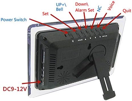
Image 5.1: Rear view of the clock with control buttons and power input labeled.
Electronic Calendar Setting Instructions:
- Power On: Power on the device and press the power switch button. The screen will display 'normally' and ring the bell. Any button press will stop the bell.
- Adjust Calendar and Time: On the main interface, press the "ENTER" button once. The 'year' of the calendar will flicker. Adjust the year using the UP or DOWN buttons. After adjusting, press "ENTER" again to enter the 'month' setting. Continue this process to set the year, month, hour, and minutes. After setting, press the "RETURN" key to return to the main interface, or wait 20 seconds for it to automatically return.
- Set Ring Bell: On the main interface, press the UP button once, and the ring light will illuminate.
- Set Alarm Clock and Birthday Reminder: On the main interface, press the DOWN button to enter the alarm clock and birthday setting. The display will show "A1" (Alarm 1), indicating hour and minute. Press DOWN again to cycle through the next alarm clocks (A1-A8). To set an alarm, press the "ENTER" button when the desired alarm clock is flickering. The alarm hour will flicker. Adjust the hour using the UP or DOWN buttons. After setting, press "ENTER" to set the alarm minute. When the alarm clock is set, the alarm icon will light up, indicating the alarm is active.
- Cancel Alarm: On the main interface, press the DOWN button to enter the alarm screen. Navigate to the alarm you wish to cancel, then press UP once. The alarm display will change to "--:--", indicating it is canceled.
- Set 12H/24H and Celsius/Fahrenheit: These settings are configured on the circuit board. You will need to unplug the power supply and remove the 3V backup battery to access the jumpers.
- 12H/24H Setting: Find the 12H/24H jumper welding plate on the back of the circuit board. Break it to set 24 hours, and short circuit it to set 12 hours.
- Celsius/Fahrenheit Setting: Find the Celsius/Fahrenheit jumper welding plate. Disconnect Celsius to set Fahrenheit, and short circuit it to set Celsius.
6. Operating Instructions
Once your clock is assembled and set up, it offers several daily functions:
- Time Display: The 1-inch large digital tube continuously displays the current time.
- Calendar and Temperature Display: The 0.5-inch digital tube displays the current date and real-time temperature.
- Power Saving Mode: Utilize the one-button switch to activate power saving mode, reducing display brightness or turning off the display when not actively viewed.
- Alarm Function: The clock supports up to 8 independent alarm settings. When an alarm triggers, the loud alarm horn will sound, or the simulated bell ring/cuckoo sound will play.
- Birthday Reminder: Set up to 12 birthday reminders, which will alert you on the specified dates.
- Time and Temperature Units: Easily switch between 12-hour and 24-hour time formats, and between Celsius and Fahrenheit for temperature display, as configured during setup.
- Wall Mounting: The clock features a bracket and a hole on the back, allowing for tabletop placement or wall mounting.
- Power Failure Memory: In case of a power outage, the clock retains its settings, eliminating the need for re-setup once power is restored.
7. Maintenance
To ensure the longevity and optimal performance of your DONGKER ECL-1227 Digital Electronic Clock Kit, follow these simple maintenance guidelines:
- Cleaning: Gently wipe the display and casing with a soft, dry, or slightly damp cloth. Avoid using abrasive cleaners, solvents, or excessive moisture, which can damage the electronic components or finish.
- Placement: Place the clock in a stable location, away from direct sunlight, extreme temperatures, high humidity, and strong magnetic fields.
- Backup Battery: The clock uses a 3V backup battery (CR2025) to maintain settings during power outages. If the clock consistently loses time or settings after a power interruption, the backup battery may need replacement. Refer to the assembly section for accessing the circuit board to replace the battery.
- Avoid Disassembly: Unless performing specific adjustments as outlined in the setup section (e.g., 12H/24H jumper), avoid unnecessary disassembly, as this may damage components or void any potential warranty.
8. Troubleshooting
If you encounter issues with your DONGKER ECL-1227 clock kit, consider the following troubleshooting steps:
- Clock Does Not Power On:
- Ensure the power adapter is correctly connected and plugged into a working outlet.
- Verify that the power switch on the clock is in the 'ON' position.
- Inspect the power socket and connections on the PCB for any loose or poorly soldered joints.
- Display Issues (e.g., blank, flickering, incorrect segments):
- Check all solder joints for the digital display modules (Digitrons) and their associated driver ICs. Re-solder any 'cold' or incomplete joints.
- Ensure the display modules are inserted correctly and fully seated.
- Verify that the main control IC (U1, T2518) is correctly installed and soldered.
- Incorrect Time/Date or Settings Not Saved:
- Confirm that the time and date settings were correctly entered as per Section 5.
- Check the 3V CR2025 backup battery. If it's depleted, the clock will lose settings during power outages. Replace if necessary.
- Ensure the crystal oscillator (X1, 32768Hz) is correctly soldered and functional, as it is crucial for accurate timekeeping.
- Buttons Not Responding:
- Inspect the soldering of the push buttons (SW1-SW7) on the PCB.
- Ensure the buttons are not physically stuck or obstructed by the casing.
- Alarm Not Sounding:
- Verify that the alarm is correctly set and activated (alarm icon lit).
- Check the speaker and speaker socket connections for proper soldering and continuity.
- General Malfunction / Components Not Working:
- Re-examine all solder joints for 'pseudo/float welding' as mentioned in Section 2. This is a common cause of issues in DIY kits.
- Double-check component polarities and orientations, especially for diodes, LEDs, and electrolytic capacitors. Incorrect orientation can prevent components from working or cause damage.
- Use a multimeter to test individual components if you suspect a faulty part.
9. Specifications
| Feature | Detail |
|---|---|
| Model Number | FBM0-AAQ-13158 (ECL-1227) |
| Manufacturer | DONGKER |
| Dimensions (Parcel) | 27.3 x 16.8 x 4.9 cm |
| Item Weight | 350 g |
| Colour | Green (LED Display) |
| Style | English |
| Material | Other (Kit components) |
| Shape | Rectangular |
| Power Source | Battery Powered (Backup) / External DC (Main) |
| Display Style | Digital |
| Mounting Type | Tabletop / Wall Mount |
| Special Features | Alarm, Calendar, Temperature Display, Power Failure Memory |
| Batteries Included? | No (for main power) |
| Batteries Required? | Yes (3V CR2025 for backup, external DC power for operation) |
| Date First Available | Oct. 12 2019 |
10. Warranty and Support
For any questions regarding the DONGKER ECL-1227 Digital Electronic Clock Kit, including assembly, operation, or troubleshooting beyond the scope of this manual, please contact the manufacturer or your retailer for assistance. Please retain your proof of purchase for any warranty claims.