1. Safety Instructions
WARNING: Risk of electric shock.
- Read the manual and follow the safety instructions before operation.
- Do not remove the cover while power is applied.
- Wait for 10 minutes after disconnecting power supply to open the cover.
- Do not connect power to output terminals.
- Must securely ground (earth) the inverter.
2. Setup and Installation
2.1 Product Overview
The ATO GK3000-2S0022 VFD is designed to convert single-phase 220V-240V AC input to three-phase 220V-240V output, enabling speed control for 3-phase induction motors up to 3hp (2.2kW).

Figure 1: ATO GK3000-2S0022 VFD with control panel and side heatsink.
2.2 Basic Wiring
Ensure all wiring is correct and secure before powering on the VFD. Refer to the wiring diagrams for proper connections.
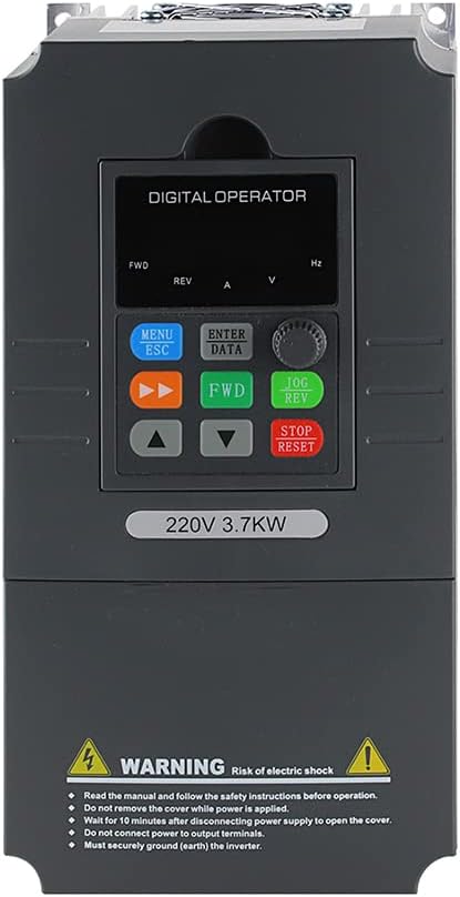
Figure 2: Front view of ATO VFD control panel with labeled buttons and display.
Power Input and Motor Output:
- Connect single-phase 220V-240V AC input to the L and N terminals.
- Connect the 3-phase motor to the U, V, and W output terminals.
- Ensure the PE (Protective Earth) terminal is properly grounded.
Control Wiring for 4-20mA Speed Control:
For 4-20mA speed control, connect a 4-20mA signal generator to the VFD. The CI terminal needs to be jumpered with I for current input. The positive (+) terminal of the signal generator connects to CI, and the negative (-) terminal connects to GND.
Video 1: Demonstrates wiring for 4-20mA speed control on the ATO VFD, showing connections for signal generator, AC power, and motor.
Control Wiring for 0-10V Speed Control:
For 0-10V speed control, connect a 0-10V signal generator to the VFD. The CI terminal needs to be jumpered with V for voltage input. The positive (+) terminal of the signal generator connects to VI, and the negative (-) terminal connects to GND.
Video 2: Illustrates wiring for 0-10V speed control using the CI port on the ATO VFD, detailing connections for the signal generator.
Control Wiring for Potentiometer & Button:
To control the VFD with a potentiometer and buttons, connect the potentiometer to +10V, VI, and GND. Connect the control buttons (FWD, REV, STOP) to X1, X2, X3, and COM terminals.
Video 3: Shows how to wire and control the ATO VFD using a potentiometer and external buttons via the VI port.
3. Operating Instructions
3.1 Initial Power-On and Basic Operation
After completing all wiring and ensuring safety, power on the VFD. The digital operator panel will display the current status. Use the FWD/REV buttons for direction control and the up/down arrows to adjust frequency.

Figure 3: Digital operator panel for VFD control.
3.2 Multi-Speed Control
The VFD supports multi-speed operation using external terminals. By configuring parameters in the P0 and P3 groups, different combinations of external switches (K1, K2, K3) can trigger preset frequencies (Pb.00 to Pb.07).
Video 4: Explains how to configure and use different VFD ports to enable various motor speeds.
3.3 Constant Pressure Pumping System
The VFD can be configured for constant pressure pumping systems using a level sensor and PID control. This ensures stable pressure with minimal energy consumption.
Video 5: Demonstrates setting up a constant pressure water pump control system with the ATO VFD.
3.4 Modbus (RS485) Control
The VFD supports RS485/Modbus-RTU protocol communication for remote control and monitoring. This allows for integration into automated systems.
Video 6: Explains how to run and stop the ATO VFD using Modbus (RS485 Port) communication.
4. Maintenance
4.1 General Care
- Keep the VFD clean and free from dust and debris.
- Ensure proper ventilation to prevent overheating.
- Regularly inspect wiring for any signs of wear or damage.
4.2 Factory Reset
To restore the VFD to factory settings, set parameter Pd.01 = 1.
5. Troubleshooting
5.1 Common Issues
- Motor not starting: Check power input, motor connections, and ensure the VFD is in run mode. Verify control signal (4-20mA, 0-10V, or button) is active.
- Incorrect frequency output: Verify parameter settings for frequency range (P0.05, P0.06, P8.04) and input signal scaling (P3.22, P3.23, P3.24 for CI port).
- VFD overload alarm: Ensure the VFD's rated current and power are greater than the motor's. Consider increasing VFD capacity by 20-30% for potential overloads.
- Motor not stopping quickly: If rapid deceleration is required for machine tools, an additional braking resistor might be necessary. Otherwise, adjust deceleration time (P0.18) and stop mode (P2.05=2 for deceleration stop/free stop).
5.2 Auto-Tuning
Auto-tuning helps the VFD optimize its performance for the connected motor. This process involves the motor rotating to determine its electrical characteristics.
Video 7: Guides through the auto-tuning process for ATO 3 Phase VFD and Single to 3 Phase VFD.
6. Specifications
| Feature | Detail |
|---|---|
| Manufacturer | ATO |
| Part Number | GK3000-2S0022 |
| Item Weight | 3.74 pounds |
| Product Dimensions | 7.24 x 3.86 x 5.31 inches |
| Item Model Number | GK3000-2S0022 |
| Style | 3hp 2.2kW |
| Material | Copper |
| Voltage | 230 Volts (AC) |
| Wattage | 2.5 KW |
| Included Components | 1*Variable Frequency Drive, 1*User Manual |
7. Warranty and Support
ATO products typically come with a manufacturer's warranty. Please refer to the product packaging or contact ATO customer service for specific warranty details.
For any questions or issues regarding the product or service, please do not hesitate to email ATO. A professional technical team is available to assist with selection, wiring, and commissioning.


