
1. Introduction
The XYGStudy CoreH743I is a compact MCU core board designed for the STM32H743IIT6 microcontroller. This board provides a minimal, ready-to-run system, making it an ideal platform for developing applications with the STM32H family of microcontrollers. It integrates essential components such as a clock circuit, USB power management, and a USB connector, and exposes all I/O ports for easy expansion and integration into custom projects.
This manual provides detailed instructions for setting up, operating, and understanding the hardware components of your CoreH743I board.

Figure 1: Top-down view of the CoreH743I STM32 MCU Core Board, showing the main microcontroller, SDRAM, and various connectors.
2. Features
The CoreH743I board offers a robust set of features for microcontroller development:
- Microcontroller: STM32H743IIT6, a high-performance STM32 MCU.
- Core: Cortex-M7 32-bit RISC with double-precision FPU and Chrom-ART graphic accelerator.
- Operating Frequency: Up to 480MHz, 1027 DMIPS/2.14 DMIPS/MHz.
- Operating Voltage: 1.62V-3.6V.
- Memory: 2MB Flash, 1MB RAM (864KB User + 192KB TCM + 4KB Backup).
- Onboard SDRAM: 64M Bit (8MB) IS42S16400J.
- I/O Expansion: All I/O ports are accessible via 2.0mm pitch pin headers.
- Debugging/Programming: JTAG/SWD interface for programming and debugging, supports IAP.
- Connectivity: USB Type-C connector for power and USB communication.
- Power Management: Onboard AMS1117-3.3 for 3.3V voltage regulation.
- Clock Circuit: Integrated 8MHz crystal and 32.768K crystal for internal RTC.
- Minimal System: Integrates clock circuit, USB power management, and USB connector for immediate use.
3. Package Contents
Please verify that all items listed below are included in your package:
- CoreH743I MCU Core Board x 1
- USB Type-A plug to Micro-B plug cable x 1

Figure 2: Package contents including the CoreH743I board and USB cable.
4. Setup
Follow these steps to set up your CoreH743I board:
- Power Connection: Connect the provided USB cable to the USB connector on the CoreH743I board and plug the other end into a USB port on your computer or a 5V USB power adapter. The PWR LED (Power Indicator) should illuminate, indicating the board is receiving power.
- Driver Installation: If connecting to a computer for the first time, your operating system may attempt to install necessary USB drivers. Ensure these drivers are successfully installed.
- Development Environment: Install an appropriate Integrated Development Environment (IDE) for STM32 microcontrollers, such as STM32CubeIDE, Keil MDK-ARM, or IAR Embedded Workbench. You will also need the STM32CubeProgrammer for flashing firmware.
- JTAG/SWD Debugger (Optional): For programming and debugging, connect an external JTAG/SWD debugger (e.g., ST-Link, J-Link) to the JTAG/SWD interface on the CoreH743I board.
- Initial Firmware: Refer to the STM32 documentation and examples for your chosen IDE to load your first program onto the STM32H743IIT6.
5. Operating the CoreH743I
The CoreH743I is a versatile development platform. Here are key operational aspects:
- Power Supply: The board can be powered via the USB connector (5V) or an external 5V supply connected to the appropriate pins on the expansion headers. Ensure the power supply switch is set correctly.
- Programming and Debugging: Use the JTAG/SWD interface with a compatible debugger to upload firmware and debug your applications.
- Boot Mode Selection: The BOOT0 pin (via a jumper or switch) allows you to select the boot mode (e.g., boot from Flash, boot from System Memory for DFU). Refer to the STM32H7 reference manual for specific boot configurations.
- I/O Expansion: Utilize the exposed I/O pins to connect peripherals, sensors, and other components to your STM32H743IIT6 microcontroller.
- USB Functionality: The USB connector supports device, host, and OTG modes. Configure the OTG jumper as needed for your application.
6. Hardware Overview and Pinout
This section details the main components and pin assignments of the CoreH743I board.
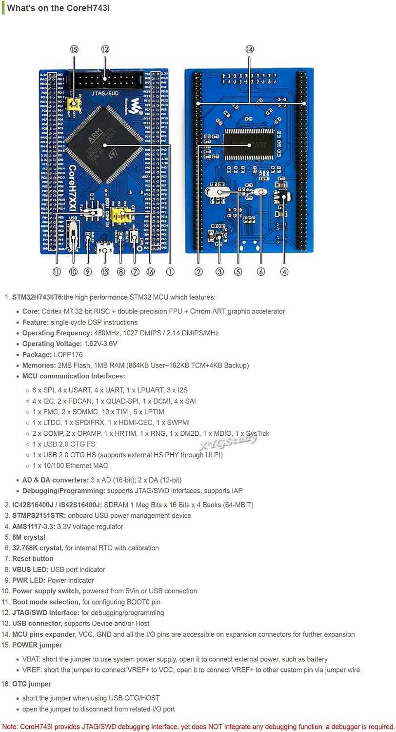
Figure 3: Detailed hardware overview of the CoreH743I board.
Key Components:
- STM32H743IIT6: The main microcontroller unit.
- IS42S16400J: 64M Bit (8MB) SDRAM for external memory.
- AMS1117-3.3: 3.3V voltage regulator.
- 8M Crystal: Main oscillator for the MCU.
- 32.768K Crystal: For Real-Time Clock (RTC) calibration.
- Reset Button: To reset the microcontroller.
- VBUS LED: USB port indicator.
- PWR LED: Power indicator.
- Power Supply Switch: Selects power source (5Vin or USB connection).
- Boot Mode Selection: Jumper for configuring BOOT0 pin.
- JTAG/SWD Interface: For debugging and programming.
- USB Connector: Supports Device/Host/OTG port.
- MCU Pins Expander: VCC, GND, and all the I/O pins are accessible on expansion connectors for further expansion.
- Power Jumper:
- VREF+: Short the jumper to use system power supply.
- Open: Open it to connect external power, such as a battery.
- VREF+ to other custom pin: Via jumper wire.
- OTG Jumper:
- Short: When using USB OTG/Host.
- Open: To disconnect from related I/O port.
Note: CoreH743I provides JTAG/SWD debugging interface, yet does NOT integrate any debugging function. A debugger is required.
7. Specifications
| Feature | Description |
|---|---|
| Brand | XYGStudy |
| Model Name | CoreH743I |
| Microcontroller | STM32H743IIT6 |
| CPU Manufacturer | STMicroelectronics |
| RAM Memory Technology | SDRAM (64M Bit onboard) |
| Connectivity Technology | USB |
| Total USB Ports | 1 (Type-C) |
| Dimensions (L x W) | 83.00 mm x 57.62 mm |
| Weight | 0.075 kg |
| UPC | 719209006880 |

Figure 4: Dimensions of the CoreH743I board in millimeters.
8. Maintenance
To ensure the longevity and proper functioning of your CoreH743I board, follow these maintenance guidelines:
- Handle with Care: Electronic components are sensitive. Avoid dropping the board or subjecting it to physical shock.
- Static Discharge: Always handle the board in an ESD-safe environment or take precautions to discharge static electricity from your body before touching the board.
- Keep Dry: Protect the board from moisture, humidity, and liquids, which can cause short circuits and damage.
- Cleanliness: Keep the board free from dust and debris. Use a soft, dry brush or compressed air to gently clean the surface if necessary. Do not use liquid cleaners.
- Storage: When not in use, store the board in an anti-static bag in a cool, dry place.
9. Troubleshooting
If you encounter issues with your CoreH743I board, consider the following troubleshooting steps:
- No Power Indicator (PWR LED off):
- Check the USB cable connection. Try a different USB port or cable.
- Ensure the power supply switch is in the correct position for your power source.
- Verify your USB power source is providing sufficient power (5V).
- Board Not Recognized by Computer:
- Ensure USB drivers are correctly installed. Check Device Manager (Windows) or System Information (macOS/Linux) for unrecognized devices.
- Try a different USB cable or port.
- Programming/Debugging Issues:
- Verify the JTAG/SWD debugger is correctly connected to the board and your computer.
- Ensure your IDE and debugger drivers are up to date.
- Check the boot mode selection jumper (BOOT0) if you are having trouble flashing.
- Confirm the target voltage settings in your debugger software match the board's voltage (3.3V).
- Application Not Running as Expected:
- Review your code for logical errors.
- Check pin assignments and peripheral configurations in your software against the board's pinout.
- Use the debugger to step through your code and inspect variable values.
10. Warranty and Support
For warranty information, technical support, or further assistance with your XYGStudy CoreH743I board, please contact the seller directly through the platform where you purchased the product. Provide your order details and a clear description of the issue to facilitate a prompt response.
Additional resources, including datasheets and example code, may be available from the manufacturer or through online community forums dedicated to STM32 development.