
1. Introduction
This manual provides comprehensive instructions for the installation, operation, and maintenance of the SOMMER Twist 200E 2-Wing Gate Opener system. The Twist 200E is designed for both left and right-hand gate applications and supports both single and double-leaf gate operation. It features a controlled smooth movement that reduces speed before reaching end positions, protecting both the gate and the mechanical components.
Key features include a pedestrian gate function, allowing only one gate leaf to open for pedestrian access, and an automatic closing function that ensures the gate closes after a set time once the light barrier is passed.
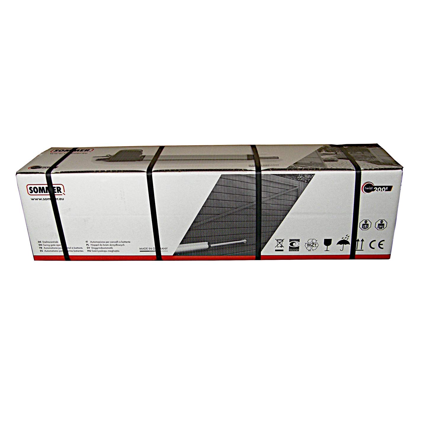
Figure 1: Complete SOMMER Twist 200E Gate Opener Kit, including two gate motors, control unit, remote controls, photocell, and warning light.
2. Safety Information
Read all safety warnings and instructions carefully before installing and operating the gate opener. Failure to follow these instructions may result in serious injury or property damage. Keep this manual for future reference.
- Ensure all electrical connections are made by a qualified electrician and comply with local regulations.
- Do not allow children to play with or operate the gate opener controls.
- Keep hands and clothing clear of the gate and moving parts during operation.
- Regularly inspect the gate opener system for signs of wear, damage, or misalignment.
- In case of power failure, use the manual release mechanism to operate the gate.
- Install the warning light in a visible location to alert pedestrians and vehicles of gate movement.
3. Components Overview
The SOMMER Twist 200E system typically includes the following components:
- 2 x Twist 200E Swing Gate Motors: The primary actuators for opening and closing the gate leaves.
- 1 x Control Unit in Post Housing: Contains the main electronics, radio receiver (FM 868.8 MHz Somloq Rolling Code), and connection terminals.
- 2 x 2-Channel Hand Transmitters (Model 4026 V000): Remote controls for operating the gate.
- 1 x Disposable Photocell (Model 7029 V000): Safety device to detect obstructions in the gate's path.
- 1 x LED Warning Light 24 V (Model 5114V000): Provides visual indication during gate operation.
- Mounting Hardware: Bolts, nuts, and brackets for securing the motors and other components.

Figure 2: The main control unit, housed in a protective casing, responsible for managing gate operations and receiving signals from remote controls.

Figure 3: SOMup4 radio receiver module, integrated into the control unit for wireless communication with hand transmitters.
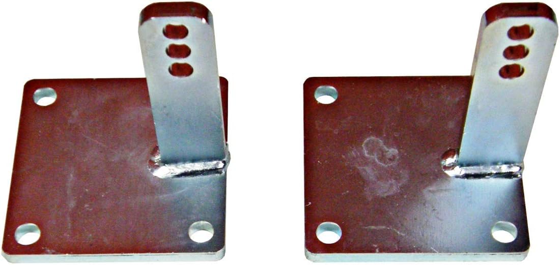
Figure 4: Two 2-channel hand transmitters (remote controls) for convenient operation of the gate opener.

Figure 5: The 24V LED warning light, designed to provide visual alerts during gate movement for enhanced safety.
4. Setup and Installation
Installation of the SOMMER Twist 200E requires careful attention to mechanical and electrical connections. It is recommended that installation be performed by a qualified professional.
4.1 Mechanical Installation
- Mount the two Twist 200E gate motors to the gate posts and gate leaves using the provided mounting hardware. Ensure correct alignment for smooth operation.
- Install the photocell units on opposite sides of the gate opening, ensuring they are aligned and free from obstructions.
- Securely mount the LED warning light in a prominent position where it is clearly visible to approaching traffic and pedestrians.
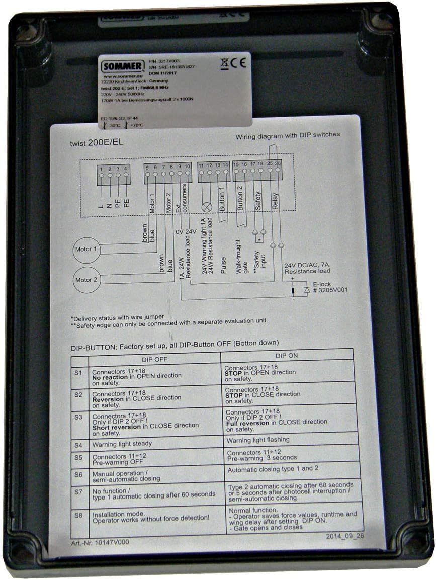
Figure 6: Various bolts, nuts, and small brackets included for securing the gate opener components during installation.

Figure 7: Robust metal brackets designed for secure attachment of the gate motors to the gate structure.
4.2 Electrical Connections and Wiring
Connect the gate motors, photocell, warning light, and power supply to the control unit according to the wiring diagram. Ensure all connections are secure and properly insulated.

Figure 8: Detailed wiring diagram for the Twist 200E/EL control unit, showing connections for motors, safety devices, and power, along with DIP switch configurations.
Refer to Figure 8 for the specific wiring diagram. Pay close attention to the polarity and terminal assignments for each component.
5. Operating Instructions
5.1 Basic Operation
Use the provided 2-channel hand transmitters to operate the gate. Pressing a programmed button will initiate the gate's movement (open or close).
5.2 Pedestrian Gate Function
The pedestrian gate function allows only one leaf of the gate to open, providing convenient access for pedestrians or cyclists without fully opening both gate leaves. This function can be activated via a dedicated button on the hand transmitter or configured through the control unit settings.
5.3 Automatic Closing
With the automatic closing function enabled, the gate will automatically close after a pre-set time once the light barrier (photocell) has been cleared. This ensures the gate is always secured behind you. The delay time for automatic closing can be adjusted in the control unit settings.
6. Maintenance
Regular maintenance ensures the longevity and reliable operation of your SOMMER Twist 200E gate opener. Perform the following checks periodically:
- Visual Inspection: Check all mechanical components (hinges, mounting brackets, gate leaves) for wear, corrosion, or damage.
- Cleanliness: Keep the photocell lenses clean and free from dirt, dust, or spiderwebs to ensure proper function.
- Lubrication: Lubricate moving parts of the gate and motors as recommended by the manufacturer (refer to the full manual for specific lubrication points and types).
- Cable Inspection: Inspect all electrical cables for signs of fraying, cuts, or damage.
- Functionality Test: Periodically test the safety features, such as the photocell, to ensure they are working correctly.
7. Troubleshooting
This section addresses common issues you might encounter with your SOMMER Twist 200E gate opener. For more complex problems, consult a qualified technician.
7.1 DIP Switch Settings
The control unit features DIP switches for configuring various operational parameters. Refer to Figure 8 for the location of the DIP switches and the table below for their functions.
| DIP Switch | DIP OFF (Bottom down) | DIP ON |
|---|---|---|
| S1 | Connectors 17+18: No reaction in OPEN direction on safety. | Connectors 17+18: STOP in OPEN direction on safety. |
| S2 | Connectors 17+18: No reaction in CLOSE direction on safety. | Connectors 17+18: STOP in CLOSE direction on safety. |
| S3 | Connectors 17+18: Only DIP 2 OFF! Short reversion in CLOSE direction on safety. | Connectors 17+18: Only DIP 2 OFF! Full reversion in CLOSE direction on safety. |
| S4 | Warning light steady. | Warning light flashing. |
| S5 | Connectors 11+12: Pre-warning 0 seconds. | Connectors 11+12: Pre-warning 3 seconds. |
| S6 | Manual operation / Semi-automatic closing. | Automatic closing type 1 and 2. |
| S7 | No function / Type 1 automatic closing after 60 seconds. | Type 2 automatic closing after 60 seconds with 0.5 second pre-warning / semi-automatic closing. |
| S8 | Installation mode: Operator works without force detection! | Normal function: Operator with force values, runtime and wing delay after setting DIP ON. Data opens and closes. |
7.2 Common Issues
- Gate not responding to remote: Check battery in remote, ensure radio receiver (SOMup4) is correctly installed and powered, verify remote is programmed.
- Gate stops unexpectedly: Check photocell for obstructions or dirt. Inspect safety edges (if installed) for activation. Review DIP switch settings for safety reactions (S1, S2, S3).
- Gate not closing automatically: Ensure automatic closing function is enabled via DIP switch (S6, S7) and the photocell is clear.
- Warning light not functioning: Check wiring to the warning light and ensure DIP switch S4 is set correctly.
8. Specifications
- Model: Twist 200E (3217V200)
- Manufacturer: SOMMER Antriebs- und Funktechnik GmBH
- Product Weight: Approximately 14 kilograms (for the complete kit)
- Maximum Opening Angle: 120 degrees
- Radio Frequency: FM 868.8 MHz (Somloq Rolling Code)
- ASIN: B07V6D9NPQ
- First Available Date: July 11, 2019
9. Warranty and Support
For warranty information, technical support, or spare parts availability, please contact SOMMER Antriebs- und Funktechnik GmBH directly or refer to their official website. Information regarding software updates and spare parts availability was not provided at the time of this manual's creation.


