
1. Introduction
This manual provides essential information for the safe and effective operation of the Vikye AT1-2200X Variable Frequency Drive (VFD). The AT1-2200X is designed to convert single-phase 220V AC input into three-phase output, enabling precise speed control for 2.2kW (3HP) AC motors. It features a unique control method for high torque, high precision, and a wide speed regulating range.

Figure 1: Front view of the Vikye AT1-2200X Variable Frequency Drive.
Key features include good anti-trip performance, adaptability to various power conditions, and optimized PWM control technology for low noise and electromagnetic interference. The unit is designed with a large heat sink for efficient heat dissipation, ensuring stability and longevity.

Figure 2: Overview of the VFD's protection functions, high torque, and wide speed range capabilities.
2. Safety Precautions
WARNING: Failure to observe these precautions may result in serious injury, death, or property loss.
- Do not operate as request, may cause death, severely injured or serious property loss.
- Before wiring, please make sure to cut off the power.
- Forbid to connect U/V/W output end to AC power supply, otherwise cause damage to the inverter.
- The inverter is forbidden to install on flammables, otherwise have the risk of explosion.
- The ground terminal of the inverter must be grounded well.
- Do not install it in the environment with explosive gas, otherwise have the risk of explosion.
- Only professional people may carry on the wiring. Converter internal has high pressure, and prohibits secretly opening the shell.

Figure 3: The VFD unit displaying the safety precautions label on its front panel.
3. Setup and Installation
3.1 Mounting
The Vikye AT1-2200X VFD is designed for wall mounting. Ensure the mounting surface is stable and non-flammable. Allow adequate space around the unit for ventilation and heat dissipation, especially considering the large heat sink design.

Figure 4: Dimensions of the VFD unit, showing approximate measurements of 12.5cm (4.92 inches) by 18cm (7.08 inches) by 12.5cm (4.92 inches).
3.2 Wiring
Wiring should only be performed by qualified professionals. Ensure the main power supply is disconnected before making any connections. The VFD is designed for single-phase 220V AC input and provides three-phase output for the motor.
- Input Power: Connect the single-phase 220V AC power supply to the designated input terminals (L, N).
- Motor Output: Connect the 3-phase motor to the U, V, W output terminals. Do NOT connect these output terminals to the AC power supply.
- Grounding: Ensure the ground terminal of the inverter is properly grounded to prevent electrical hazards.
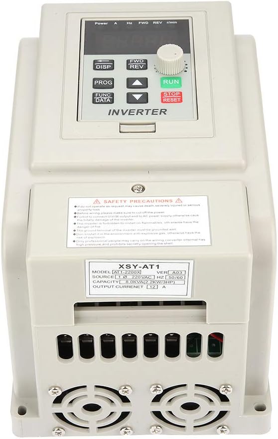
Figure 5: Bottom view of the VFD showing the input (L, N) and output (U, V, W) wiring terminals, along with the model and current specifications.
4. Operating Instructions
The VFD features an intuitive control panel for easy operation and parameter adjustment.

Figure 6: Diagram of the VFD's operation panel, highlighting the 5-digit LED display, panel potentiometer, and various control keys.
4.1 Control Panel Buttons
- 5 Digits LED Display: Shows current operating parameters and settings.
- DISP (Movement Key): Switches monitoring parameters in the monitoring state; moves the data frame to edit bits in the second-level menu.
- PROG (Programme Key): Exits the current state, switches to another state, mainly used to switch to the monitoring state.
- FUNC DATA (Function/Save Key): Enters the menu step by step, saves the set parameters.
- ▲ (Plus Key): Short/Long press to increase data and function code.
- ▼ (Minus Key): Short/Long press to decrease data and function code.
- FWD/REV (CW/CCW Key): Press to run in forward direction, release to stop. Press again for reverse operation.
- RUN (Operation Key): Initiates operation.
- STOP/RESET (Stop/Reset Key): Stops the operation of the VFD; recovers the previous wrong interface.
- Panel Potentiometer: Used for adjusting speed or frequency.
4.2 Basic Operation
- Power On: Ensure all wiring is correct and secure, then apply power to the VFD.
- Set Frequency/Speed: Use the panel potentiometer or the ▲/▼ keys to set the desired output frequency/motor speed.
- Start Motor: Press the RUN button to start the motor.
- Change Direction: Use the FWD/REV button to switch between forward and reverse rotation.
- Stop Motor: Press the STOP/RESET button to stop the motor.
For advanced parameter settings and programming, refer to the detailed programming guide (if provided separately) or consult the manufacturer's technical support.
5. Maintenance
Regular maintenance ensures the longevity and optimal performance of your VFD.
- Cleaning: Keep the VFD clean and free from dust and debris. Dust accumulation can hinder heat dissipation.
- Ventilation: Ensure that the ventilation openings and the heat sink are not obstructed. The VFD is designed with a large heat sink for effective cooling.
- Connections: Periodically check all wiring connections for tightness and signs of wear or corrosion. Loose connections can lead to poor performance or damage.
- Environment: Operate the VFD within its specified environmental conditions (temperature, humidity, dust levels) to maintain stability and prevent damage.

Figure 7: Internal view of the VFD showing the large heat sink designed for efficient heat dissipation.
6. Troubleshooting
This section provides guidance for common issues. For complex problems, contact technical support.
| Problem | Possible Cause | Solution |
|---|---|---|
| Motor does not start or runs intermittently. | Incorrect wiring, insufficient power, motor overload, incorrect parameter settings. | Verify all wiring connections. Check input voltage. Reduce motor load. Review and adjust VFD parameters. |
| VFD displays an error code. | Overload, overvoltage, undervoltage, short circuit, overheating. | Refer to the VFD's specific error code list (usually in a separate programming manual). Address the underlying cause (e.g., reduce load for overload, check power supply for voltage issues). Press STOP/RESET to clear the error. |
| Motor speed is unstable or incorrect. | Improper frequency setting, motor parameters not matched, external interference. | Adjust frequency using the potentiometer or control keys. Ensure motor parameters (e.g., rated current, frequency) are correctly set in the VFD. Check for strong electromagnetic interference. |
| Unusual noise from VFD or motor. | Loose connections, motor issues, VFD internal fault. | Check all wiring connections. Inspect the motor for mechanical issues. If noise persists and is from the VFD, contact support. |
7. Specifications
| Feature | Specification |
|---|---|
| Model Number | AT1-2200X |
| Manufacturer | Vikye |
| Input Voltage | Single-phase 220V AC |
| Output Voltage | Three-phase 220V AC |
| Rated Power | 2.2kW (3HP) |
| Current Rating | 12 Amps |
| Maximum Frequency | 400 Hz |
| Material | Copper (internal components) |
| Item Weight | 2.93 pounds |
| Product Dimensions | 47.24 x 66.93 x 59.06 inches (Note: These dimensions appear to be for packaging. The unit itself is approximately 12.5cm x 18cm x 12.5cm, as shown in Figure 4.) |
| Mounting Type | Wall Mount |
| Country of Origin | China |
8. Warranty and Support
For warranty information, technical support, or service inquiries regarding your Vikye AT1-2200X VFD, please contact the manufacturer, Vikye, or your point of purchase. Keep your purchase receipt and product model number (AT1-2200X) readily available when contacting support.
Manufacturer: Vikye