1. Introduction
This manual provides detailed instructions for the safe and effective operation of your Walfront AR860 Ultrasonic Thickness Gauge. Please read this manual thoroughly before using the device to ensure proper function and to prevent damage.
The AR860 is designed for accurate measurement of material thickness using ultrasonic principles. It is suitable for materials that are good conductors of ultrasound, including metals, plastics, ceramics, and glass.
2. Key Features
- High Accuracy: Measures thickness based on sound velocity with automatic calibration for precise measurement results.
- Material Versatility: Suitable for good ultrasonic conductors like metal, plastic, ceramic, and glass.
- Sound Velocity Settings: Offers 12 preset sound velocities for various materials.
- Data Storage: Stores up to 12 sets of thickness measurement data for convenient analysis.
- Multi-functional Display: Includes coupling status indication, thickness alarm settings, low battery warning, and automatic power-off.
- Backlit LCD Screen: Ensures clear readability even in low-light conditions.
- Portable Design: Comes with a protective storage case for easy transport.
3. Product Components
The Walfront AR860 Ultrasonic Thickness Gauge package typically includes the following items:
- AR860 Ultrasonic Thickness Gauge Unit
- Ultrasonic Probe
- Calibration Block
- Coupling Agent (may not be included, refer to packaging)
- Storage Case
- User Manual

Image 3.1: The Walfront AR860 Ultrasonic Thickness Gauge, probe, calibration block, and user manual neatly organized within its protective metal carrying case.

Image 3.2: A close-up view of the AR860 main unit, its connected ultrasonic probe, and a small circular calibration block. This image highlights the primary components used for thickness measurement.
4. Setup and Initial Operation
4.1 Battery Installation
- Locate the battery compartment on the back of the device.
- Slide open the battery cover.
- Insert 3 AAA batteries, ensuring correct polarity (+/-).
- Close the battery cover securely.

Image 4.1: The rear view of the AR860 device with the battery compartment cover removed, showing the slots for AAA batteries. This illustrates where to insert the power source.
4.2 Connecting the Probe
- Identify the two probe connectors on the top of the main unit.
- Connect the ultrasonic probe cable to these ports. Ensure a firm connection.
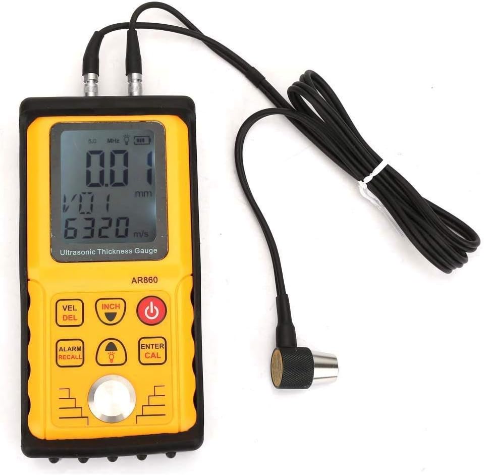
Image 4.2: The AR860 main unit with the ultrasonic probe securely connected to its top ports. This image demonstrates the correct way to attach the probe for measurement.
4.3 Powering On/Off
- Press the Power button (red button) to turn the device on.
- To turn off, press and hold the Power button, or the device will automatically shut down after 2 minutes of inactivity.
5. Operating Instructions
5.1 Understanding the Display and Buttons

Image 5.1: A detailed diagram illustrating the LCD display and the function of each button on the AR860 Ultrasonic Thickness Gauge. Key labels include LCD Display, The Probe, Sound Speed Adjustment, Select Function Entry and Thickness Storage Value Delete Key, Alarm Setting and Measurement Data Storage, Function Confirmation Key and Calibration Key, Power Switch, Speed of Sound Adjustment, Metric/Metric Conversion Key, and The Calibration Block.
- LCD Display: Shows thickness readings, sound velocity, battery status, and other indicators.
- VEL/DEL Button: Adjusts sound speed or deletes stored data.
- INCH Button: Toggles between metric (mm) and imperial (inch) units.
- Power Button: Turns the device on/off.
- ALARM/RECALL Button: Sets alarm limits or recalls stored data.
- Light Button: Toggles backlight on/off.
- ENTER/CAL Button: Confirms selections or initiates calibration.
- Up/Down Arrows: Navigate menus and adjust values.
5.2 Sound Velocity Calibration
Accurate sound velocity calibration is crucial for precise measurements. If the thickness of a material is known, its sound velocity can be used to calibrate the device.
- Ensure the probe is clean and apply a small amount of coupling agent to the calibration block.
- Press the probe firmly onto the calibration block.
- Press the ENTER/CAL button to initiate calibration. The device will display the calibrated sound velocity.
- Alternatively, you can manually select from 12 preset sound velocities using the VEL/DEL button.

Image 5.2: The AR860 display showing a sound velocity reading, indicating the device is ready for or undergoing calibration. The text emphasizes the importance of accurate sound velocity for precise thickness measurements.
5.3 Taking a Measurement
- Ensure the device is calibrated for the material you are measuring.
- Apply a small amount of coupling agent to the surface of the material to be measured.
- Press the probe firmly and perpendicularly onto the prepared surface.
- The thickness reading will appear on the LCD display.
- If the coupling status indicator shows an error, reapply coupling agent or adjust probe pressure.
5.4 Data Storage and Recall
- To store a measurement, press the ALARM/RECALL button after a stable reading is obtained. The device can store up to 12 data sets.
- To recall stored data, press the ALARM/RECALL button and use the Up/Down arrows to browse through the stored values.
- To delete stored data, use the VEL/DEL button while viewing stored data.
6. Maintenance
- Cleaning: After each use, wipe the probe and the device's surface with a soft, dry cloth. Do not use abrasive cleaners or solvents.
- Storage: Store the device in its protective case in a cool, dry place when not in use. Remove batteries if storing for extended periods to prevent leakage.
- Probe Care: Ensure the probe's contact surface is free from scratches or damage, as this can affect measurement accuracy.
7. Troubleshooting
| Problem | Possible Cause | Solution |
|---|---|---|
| No reading or unstable reading |
|
|
| Device does not power on |
|
|
| Inaccurate readings |
|
|
8. Specifications
| Parameter | Value |
|---|---|
| Model | AR860 |
| Measurement Range | 1.00 - 300.0 mm (Steel) |
| Accuracy | ±(1%H + 0.1) mm |
| Sound Velocity Range | 1000 - 9999 m/s |
| Operating Frequency | 5 MHz |
| Data Storage | 12 sets |
| Display | LCD with backlight |
| Power Supply | 3 x 1.5V AAA Batteries |
| Automatic Shutdown | After 2 minutes of inactivity |
| Dimensions (L x W x H) | 15.3 x 7.5 x 3.5 cm |
| Weight | Approx. 998 g (with batteries) |
| Material | Plastic |
| Operating Temperature | 0°C to 40°C (32°F to 104°F) |

Image 8.1: A diagram showing the physical dimensions of the AR860 Ultrasonic Thickness Gauge, indicating a length of 153mm and a width of 75mm.
9. Warranty and Support
For warranty information and technical support, please refer to the documentation provided with your purchase or contact your retailer. Keep your purchase receipt as proof of purchase.

