
Real HD 24 port poe gigabit switch
Contents
Real HD 24-Port Full Gigabit PoE+ Switch User Manual
Model: 24 port poe gigabit switch
1. Product Overview
The Real HD 24-Port Full Gigabit PoE+ Switch is an unmanaged network switch designed to simplify network setups by providing Power over Ethernet (PoE) capabilities. It features 24 Gigabit PoE ports, 2 Gigabit RJ45 uplink ports, and 2 Gigabit SFP ports, offering flexible connectivity options for various network devices. This switch is compliant with IEEE 802.3af/at network protocol standards, delivering up to 30W of power per PoE port with a total power budget of 400W.
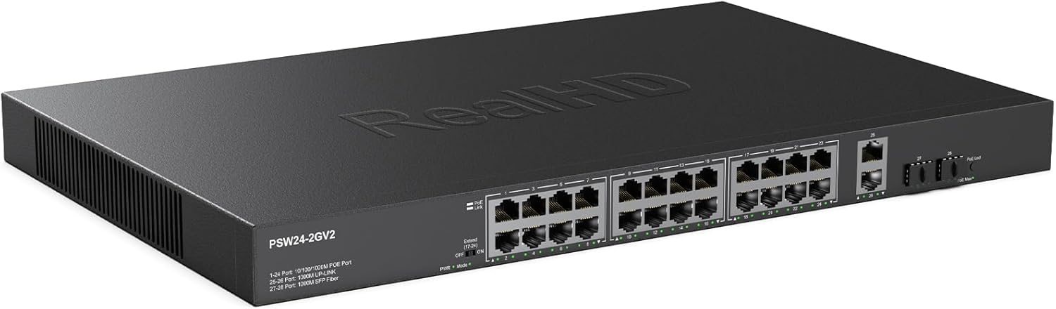
Figure 1: Real HD 24-Port Full Gigabit PoE+ Switch. This image displays the front view of the switch, highlighting its compact design and port layout.
2. Key Features
- 24 Gigabit PoE+ Ports: Provides power and data connectivity for PoE-compatible devices.
- 2 Gigabit Uplink Ports (RJ45): Dedicated ports for connecting to a router or backbone network.
- 2 Gigabit SFP Ports: Offers fiber optic connectivity for longer distances or higher bandwidth requirements.
- IEEE 802.3af/at Compliant: Ensures compatibility with standard PoE and PoE+ devices.
- 400W Total PoE Power Budget: Sufficient power for multiple high-power PoE devices.
- Up to 30W Per PoE Port: Delivers ample power for individual devices.
- Unmanaged Plug and Play: Requires no software installation or configuration for basic operation.
- Durable Metal Housing: Ensures longevity and safe operation in various environments.
- Fanless Cooling Design: Provides quiet operation and reduces dust accumulation.
- PoE Extension Function: Extends data and power transmission up to 600ft (at 10Mbps).
- VLAN Mode: Isolates ports 1-24 for enhanced security, allowing communication only with uplink ports.
- PD Detection: Automatically detects and provides the required power to PoE devices, protecting non-PoE equipment.
3. Package Contents
Verify that all items are present in the package:
- 1 x Real HD 24-Port Full Gigabit PoE+ Switch
- 1 x Dedicated Power Cord
- 1 x Quick Manual (this document)
4. Setup Instructions
4.1 Physical Installation
The switch is designed for desktop placement or 19-inch rack mounting.
- Placement: Position the switch on a stable, flat surface or install it into a standard 19-inch network rack using appropriate mounting hardware (not included). Ensure adequate ventilation around the device.
- Power Connection: Connect the provided dedicated power cord to the AC power inlet on the rear of the switch and then to a standard AC power outlet (AC100-240V 50-60Hz).
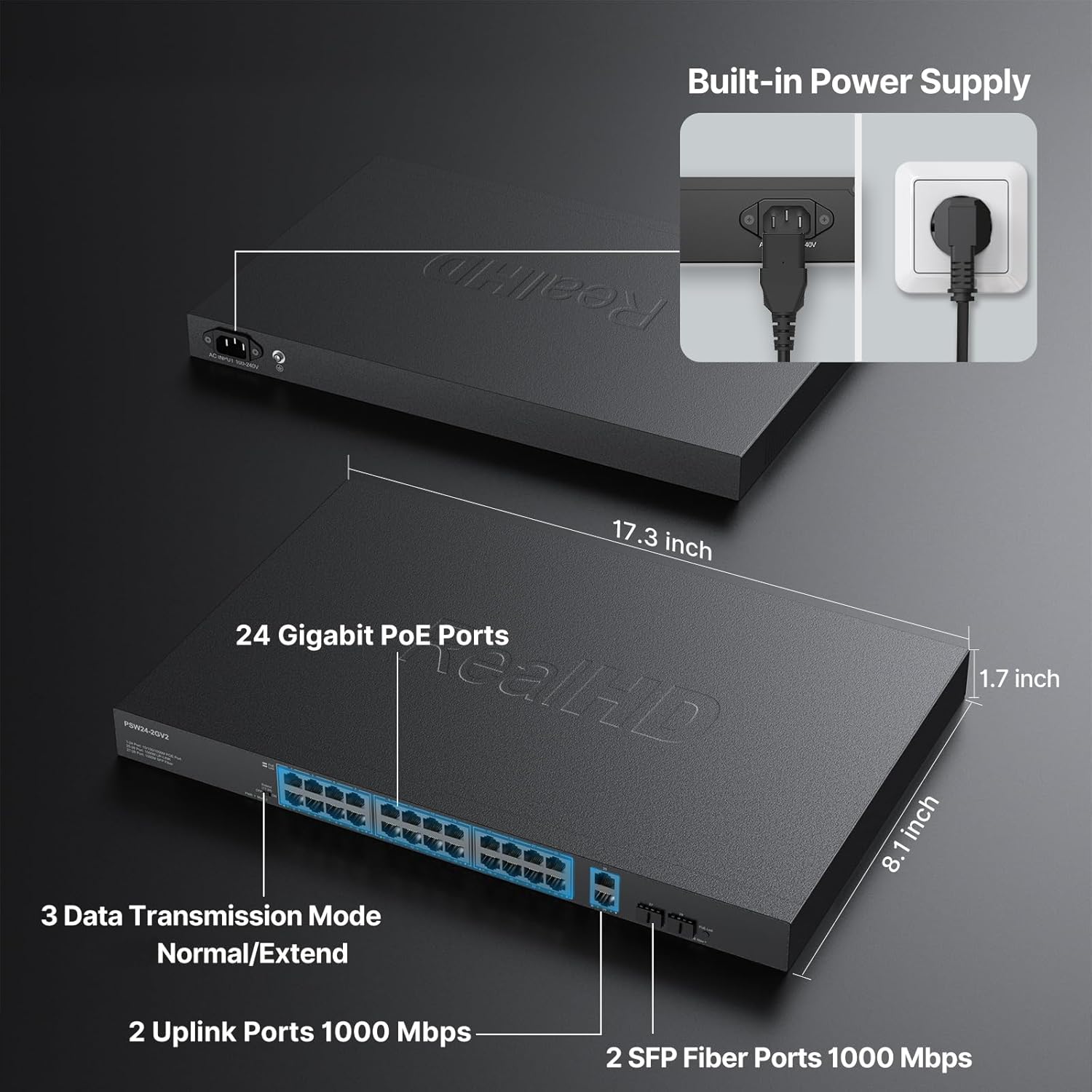
Figure 2: Built-in Power Supply and Dimensions. This image illustrates the integrated power supply and the physical dimensions of the switch, including the 24 Gigabit PoE ports, 2 Uplink Ports, and 2 SFP Fiber Ports.

Figure 3: 19-inch Rack Mount. This image demonstrates the switch installed in a standard 19-inch server rack, showcasing its compatibility with rack-mounted network environments.
4.2 Network Connections
- Connecting PoE Devices: Connect your PoE-compatible devices (e.g., IP cameras, VoIP phones, wireless access points) to any of the 24 Gigabit PoE ports using standard Ethernet cables. The switch will automatically detect and power these devices.
- Connecting Non-PoE Devices: Non-PoE network devices can also be connected to the PoE ports; the switch will only provide data connectivity without power.
- Uplink Connection: Connect one of the 2 Gigabit RJ45 uplink ports to your router, modem, or main network backbone.
- SFP Connections: For fiber optic connections, insert compatible SFP modules into the 2 Gigabit SFP ports and connect fiber optic cables as needed.
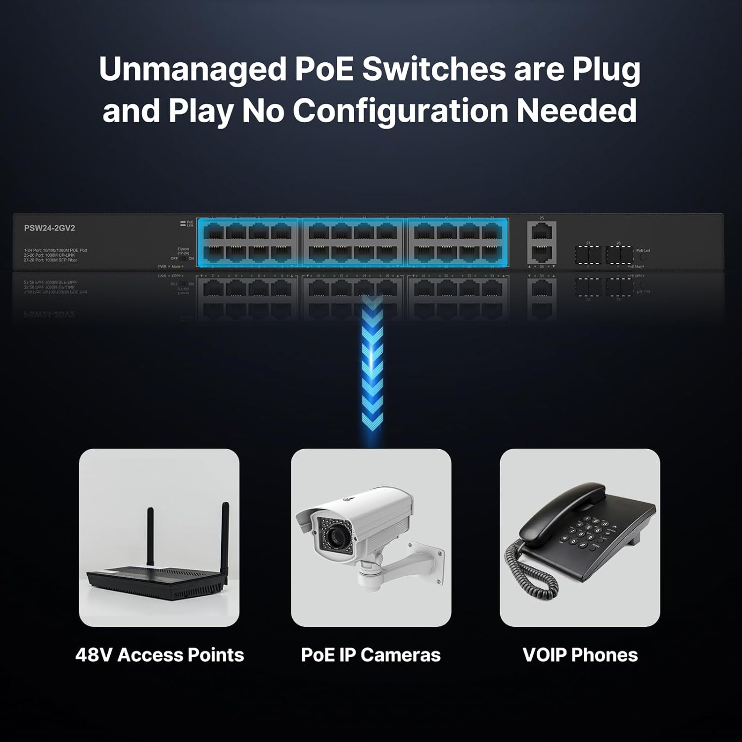
Figure 4: Unmanaged Plug and Play Connectivity. This diagram illustrates how the unmanaged PoE switch connects to various compatible devices such as 48V access points, PoE IP cameras, and VoIP phones, highlighting its plug-and-play nature.
5. Operating Instructions
5.1 Powering On
Once the power cord is connected, the switch will power on automatically. There is no power button. The LED indicators will illuminate to show operational status.
5.2 LED Indicators
The switch features LED indicators to monitor the status of each port and the device:
- Green Light: Indicates data transfer activity on the port.
- Yellow Light: Indicates PoE power is ON for the port.
5.3 Extend Function
The switch includes an 'Extend' function, typically controlled by a physical switch on the device. When activated, this function allows PoE power and data transmission distance to be extended up to 600 feet (approximately 183 meters). Note that when the Extend function is operating, the transmission speed for the affected ports will be reduced to 10Mbps. High-quality Ethernet cables are recommended for optimal performance over extended distances.

Figure 5: Extend PoE Function. This image visually explains the PoE extension capability, showing that in default mode, 10/100/1000 Mbps is supported up to 300ft, while in extend mode, 10 Mbps is supported up to 600ft.
5.4 VLAN Mode (Port Isolation)
For enhanced security, the switch supports a VLAN mode, also typically controlled by a physical switch. When enabled, ports 1-24 are isolated from each other, meaning devices connected to these ports cannot directly communicate with each other. They can, however, communicate with the uplink ports, allowing them to access the main network while maintaining isolation from other local devices on the switch.

Figure 6: Isolated for Enhanced Security. This diagram illustrates how, in VLAN mode, ports 1-24 are isolated from each other but can communicate with the uplink ports, enhancing network security for connected devices like surveillance cameras.
6. Maintenance
The Real HD PoE switch is designed for reliable operation with minimal maintenance.
- Cleaning: Keep the switch clean and free from dust. Use a soft, dry cloth for cleaning. Do not use liquid or aerosol cleaners.
- Ventilation: Ensure that the ventilation openings are not blocked to allow for proper heat dissipation. The fanless design helps prevent dust build-up internally.
- Environment: Operate the switch within its specified temperature and humidity ranges to ensure optimal performance and longevity.

Figure 7: Fanless Cooling Design. This image highlights the benefits of the fanless cooling design, including zero noise, no dust build-up, rugged metal case, quiet and stable operation, 4KV surge protection, and less heat generation.
7. Troubleshooting
If you encounter issues with your Real HD PoE switch, refer to the following common troubleshooting steps:
- No Power: Ensure the power cord is securely connected to both the switch and a working power outlet. Check the power outlet with another device.
- No Link/Activity: Verify that Ethernet cables are properly connected to both the switch and the network device. Check the corresponding LED indicators for link status and activity. Try a different cable or port.
- PoE Device Not Powering On: Confirm that your device is PoE-compatible (IEEE 802.3af/at standard). This switch does not support passive 24V PoE devices (e.g., some Ubiquiti access points). Check the yellow PoE LED for the port. Ensure the total power budget of 400W is not exceeded by all connected PoE devices.
- Slow Network Speed: If the 'Extend' function is enabled, the speed will be limited to 10Mbps. Disable 'Extend' mode if full Gigabit speed is required and devices are within 300ft. Ensure high-quality Ethernet cables are used.
- Device Isolation: If devices on ports 1-24 cannot communicate with each other, check if VLAN mode (port isolation) is enabled. Disable it if direct communication between these ports is desired.
8. Specifications
| Feature | Specification |
|---|---|
| Model Number | 24 port poe gigabit switch |
| Ports | 24 x 10/100/1000 Mbps PoE ports, 2 x 10/100/1000Mbps Gigabit SFP ports, 2 x Gigabit RJ45 Uplink Ports |
| PoE Standard | IEEE 802.3af/at |
| PoE Power Output (Per Port) | Up to 30W |
| Total PoE Power Budget | 400W |
| Bandwidth | 56Gbps |
| MAC Address Table Size | 2K |
| Power Supply | AC100-240V 50-60Hz (Internal Power Supply) |
| Voltage | 48 Volts (DC output for PoE) |
| Case Material | Metal |
| Product Dimensions (L x W x H) | 17.3" x 8.1" x 1.7" (43.9cm x 20.6cm x 4.3cm) |
| Item Weight | 9.38 pounds (4.26 Kilograms) |
| Operating Temperature | Up to 131°F (55°C) |
| Compatible Devices | 48V access points, PoE IP cameras, VOIP phones, Desktop PCs, Printers, PoE NVRs, Laptops |

Figure 8: Power Budget and Output. This image highlights the switch's 400W total power budget and the capability to deliver up to 30W of power per port, suitable for continuous operation of PoE systems.
9. Warranty and Support
Real HD is committed to providing reliable products and customer satisfaction. If you encounter any problems or have concerns regarding your 24-Port Full Gigabit PoE+ Switch, please contact our customer support team.
- Customer Service: Our dedicated team aims to respond to inquiries and resolve issues within 24 hours. Please refer to your purchase documentation or the Real HD website for specific contact details.
- Protection Plans: Extended protection plans may be available for purchase separately to cover your device beyond the standard warranty period.
Ask a question about this manual
Ask about setup, troubleshooting, compatibility, parts, safety, or missing instructions. Manuals+ will review the question and use this page’s manual context to help answer it.