1. Introduction
This manual provides instructions for the Vikye DC 5V/12V/24V Delay Timer Relay. This module is designed for various control applications requiring precise timing, including delay ON, delay OFF, self-locking, and trigger delay functions. It features stable performance, simple operation, and power supply anti-reverse protection.
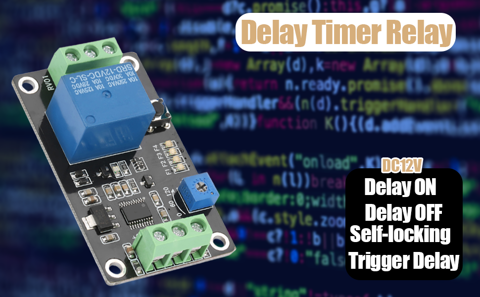
Image 1.1: Vikye Delay Timer Relay highlighting its key functions.
The module is pre-programmed with four functions and allows for customization. Its parameters are saved automatically, preventing loss upon power-off. The delay time is adjustable from 0.1 seconds to 120 seconds.
2. Product Components
The Vikye Delay Timer Relay module consists of several key components:
- Power Input Terminals (DC+, DC-): For connecting the DC power supply (5V, 12V, or 24V depending on the model).
- Signal Input Terminal (X1): For trigger signals.
- Relay Output Terminals (COM, NO, NC): Common, Normally Open, and Normally Closed contacts for controlling external devices.
- Potentiometer (0-120): Used to adjust the delay time.
- SET Button: For configuring operating modes.
- Indicator LEDs (F1, F2, F3, F4): Indicate the currently selected operating mode.

Image 2.1: Labeled diagram of the relay module showing input/output terminals and controls.

Image 2.2: General view of the Vikye Delay Timer Relay module.
3. Setup and Wiring
Proper wiring is essential for safe and correct operation. Ensure the power supply matches the module's voltage (5V, 12V, or 24V).
- Power Connection: Connect the DC power supply to the terminals labeled DC+ and DC-. Ensure correct polarity to prevent damage to the module. The module includes power supply anti-reverse protection.
- Load Connection: The relay contacts (COM, NO, NC) are isolated from the module's power input. Connect your external load (e.g., light, motor) to these terminals.
- COM (Common): Connect one side of your load's power source here.
- NO (Normally Open): The circuit between COM and NO is open when the relay is de-energized and closes when energized.
- NC (Normally Closed): The circuit between COM and NC is closed when the relay is de-energized and opens when energized.
- Trigger Input (X1): If using a trigger function, connect your trigger signal to the X1 terminal.


Image 3.1: Detailed view of input (left) and output (right) terminals for wiring.
4. Operating Instructions
The module offers multiple operating modes and adjustable delay times.
4.1 Setting Operating Modes
The module has four preset functions (F1, F2, F3, F4). To change the operating mode:
- Press and hold the SET button until the indicator LEDs (F1-F4) begin to flash.
- Briefly press the SET button repeatedly to cycle through the available modes (F1, F2, F3, F4). The corresponding LED will illuminate.
- Once the desired mode is selected, press and hold the SET button again until the LEDs stop flashing to confirm and save the mode.
Refer to the product documentation or online resources for detailed descriptions of each mode (Delay ON, Delay OFF, Self-locking, Trigger Delay).
4.2 Adjusting Delay Time
The delay time can be set between 0.1 seconds and 120 seconds using the onboard potentiometer.
- Locate the blue potentiometer labeled "0-120" on the module.
- Use a small screwdriver to carefully turn the potentiometer. Turning it clockwise increases the delay time, and counter-clockwise decreases it.
- The value corresponds to seconds. For example, setting it to "60" will result in a 60-second delay.

Image 4.1: Potentiometer for time adjustment and SET button for mode selection.
5. Specifications
Key technical specifications for the Vikye Delay Timer Relay:
| Feature | Specification |
|---|---|
| Brand | Vikye |
| Coil Voltage | 12 Volts (DC) - Note: Available in 5V, 12V, 24V variants. This manual refers to the 12V model. |
| Current Rating | 10 Amps |
| Maximum Switching Current | 10 Amps |
| Minimum Switching Voltage | 5 Volts (DC) |
| Contact Type | Normally Closed, Normally Open |
| Contact Material | Silver |
| Connector Type | Wired |
| Mounting Type | Panel Mount |
| Operation Mode | On Off (Delay functions) |
| Delay Time Range | 0.1 seconds to 120 seconds |
| Product Dimensions | 1.97 x 1.57 x 0.79 inches (50 x 40 x 20 mm) |
| Item Weight | 0.704 ounces (20 grams) |

Image 5.1: Dimensions of the relay module.
6. Troubleshooting
- Module does not power on:
- Verify that the DC power supply voltage matches the module's rating (e.g., 12V for a 12V module).
- Check the polarity of the power connection to DC+ and DC-. Although the module has anti-reverse protection, incorrect wiring can prevent operation.
- Ensure power supply is active and providing sufficient current.
- Relay does not switch or output no voltage:
- Confirm the module is powered on and the selected operating mode is appropriate for your application.
- Check the wiring to the COM, NO, and NC terminals. Remember that the relay contacts are isolated; you must provide power to the COM terminal for your load.
- If using a trigger function, ensure the trigger signal is correctly applied to X1 and is within the expected voltage range.
- Verify the delay time setting on the potentiometer.
- Inspect for any visible damage to the relay or circuit board.
- Incorrect delay time:
- Adjust the potentiometer carefully. Small adjustments can significantly change the delay.
- Ensure the potentiometer is not at its extreme limits if you expect an intermediate delay.
7. Maintenance
The Vikye Delay Timer Relay module is designed for reliable operation with minimal maintenance.
- Cleaning: Keep the module free from dust and debris. Use a soft, dry cloth for cleaning. Avoid using liquids or abrasive cleaners.
- Environment: Operate the module within its specified temperature and humidity ranges. Avoid exposure to extreme conditions, moisture, or corrosive substances.
- Connections: Periodically check all wiring connections to ensure they are secure and free from corrosion.
8. Warranty and Support
For warranty information or technical support, please contact Vikye customer service through your purchase platform or the official Vikye website. Please have your product model and purchase date available when contacting support.
For general inquiries, you may visit the Vikye store on Amazon.


