
1. Introduction
The MASTECH MS8260E is a versatile 2000-count digital multimeter designed for a wide range of electrical and electronic measurements. It features a large LCD display, non-contact voltage (NCV) detection, and capabilities for measuring AC/DC voltage, AC/DC current, resistance, capacitance, and inductance. This manual provides essential information for the safe and effective operation, maintenance, and troubleshooting of your device.
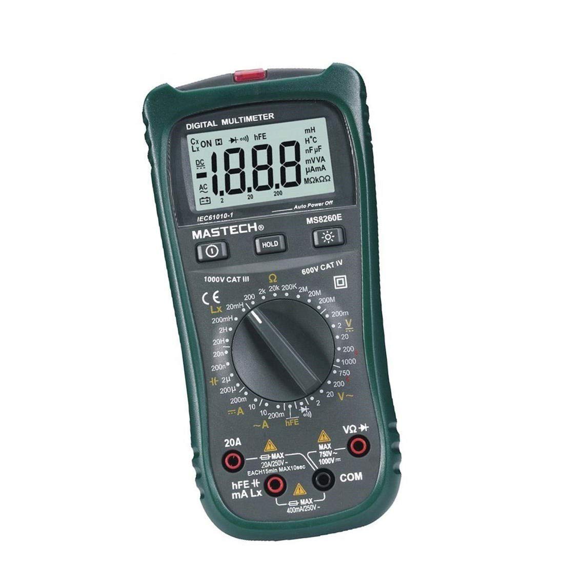
Figure 1: Front view of the MASTECH MS8260E Digital Multimeter, showing the LCD display, function rotary switch, and input jacks.
2. Safety Information
To ensure safe operation and service of the meter, follow these safety guidelines:
- Read and understand all instructions in this manual before using the meter.
- Always adhere to local and national safety codes.
- Do not use the meter if it appears damaged or if the insulation on the test leads is compromised.
- Observe the input limits for each measurement range to prevent electrical shock or damage to the meter. This meter is rated for CAT.IV 600V.
- Use caution when working with voltages above 30V AC RMS, 42V peak, or 60V DC. These voltages pose a shock hazard.
- Always disconnect power to the circuit and discharge all high-voltage capacitors before making resistance, continuity, diode, or capacitance measurements.
- Replace the battery immediately when the low battery indicator appears to ensure accurate readings.
- Do not operate the meter in explosive gas, vapor, or dust environments.
3. Product Overview
The MS8260E multimeter is equipped with several features to facilitate accurate and convenient measurements:
- Large 2000 Counts LCD Display: Provides clear digital readings.
- Built-in Non-Contact Voltage (NCV) Detector: Detects AC voltage greater than 110V without physical contact, indicated by a flash warning.
- Data Hold Function: Freezes the displayed reading for easy recording.
- Display Backlight: Improves visibility in dimly lit conditions.
- Auto Power Off: Conserves battery life by automatically turning off the meter after a period of inactivity.
- Low Battery Indication: Alerts the user when the battery needs replacement.
- Polarity Indication: Automatically displays negative polarity.
- 30-Range Rotary Switch: Selects various measurement functions including AC/DC voltage, AC/DC current, resistance, capacitance, inductance, diode check, continuity test, and transistor (hFE) check.
4. Setup
4.1 Battery Installation
The MS8260E requires one 9V battery (NEDA 1604/6F22). To install or replace the battery:
- Ensure the meter is turned off and disconnect all test leads from the input terminals.
- Locate the battery compartment cover on the back of the meter.
- Unscrew the retaining screw(s) and remove the cover.
- Insert the 9V battery, observing the correct polarity.
- Replace the battery compartment cover and secure it with the screw(s).
4.2 Connecting Test Leads
Always connect the black test lead to the "COM" (common) input jack. Connect the red test lead to the appropriate input jack based on the desired measurement:
- For Voltage, Resistance, Capacitance, Inductance, Diode, Continuity, and hFE measurements: Connect the red lead to the "VΩCAPHz" jack.
- For Current measurements up to 200mA: Connect the red lead to the "mA" jack.
- For Current measurements up to 10A: Connect the red lead to the "10A" jack.
Ensure test leads are fully inserted into the jacks before taking measurements.
5. Operating Instructions
Turn the rotary switch to the desired function. The meter will display "OL" (Overload) if no input is present or if the input exceeds the range.
5.1 DC Voltage Measurement (DCV)
- Set the rotary switch to the desired DCV range (200mV, 2V, 20V, 200V, 1000V).
- Connect the black test lead to the "COM" jack and the red test lead to the "VΩCAPHz" jack.
- Connect the test leads across the component or circuit to be measured, observing polarity.
- Read the voltage value on the LCD display.
5.2 AC Voltage Measurement (ACV)
- Set the rotary switch to the desired ACV range (2V, 20V, 200V, 750V).
- Connect the black test lead to the "COM" jack and the red test lead to the "VΩCAPHz" jack.
- Connect the test leads across the AC voltage source.
- Read the voltage value on the LCD display.
5.3 DC Current Measurement (DCA)
- Set the rotary switch to the desired DCA range (200mA, 10A).
- For measurements up to 200mA, connect the red lead to the "mA" jack. For measurements up to 10A, connect the red lead to the "10A" jack. The black lead connects to "COM".
- Open the circuit where current is to be measured and connect the meter in series with the load.
- Read the current value on the LCD display.
5.4 AC Current Measurement (ACA)
- Set the rotary switch to the desired ACA range (200mA, 10A).
- For measurements up to 200mA, connect the red lead to the "mA" jack. For measurements up to 10A, connect the red lead to the "10A" jack. The black lead connects to "COM".
- Open the circuit where current is to be measured and connect the meter in series with the load.
- Read the current value on the LCD display.
5.5 Resistance Measurement (Ω)
- Set the rotary switch to the desired Ω range (200Ω, 2kΩ, 20kΩ, 200kΩ, 2MΩ, 20MΩ, 200MΩ).
- Connect the black test lead to "COM" and the red test lead to "VΩCAPHz".
- Ensure the circuit is de-energized and all capacitors are discharged.
- Connect the test leads across the resistor or component.
- Read the resistance value on the LCD display.
5.6 Capacitance Measurement (CAP)
- Set the rotary switch to the desired CAP range (20nF, 200nF, 2uF, 200uF).
- Connect the black test lead to "COM" and the red test lead to "VΩCAPHz".
- Ensure the capacitor is fully discharged before connecting the test leads.
- Connect the test leads across the capacitor.
- Read the capacitance value on the LCD display.
5.7 Inductance Measurement (L)
- Set the rotary switch to the desired Inductance range (20mH, 200mH, 2H, 20H).
- Connect the black test lead to "COM" and the red test lead to "VΩCAPHz".
- Connect the test leads across the inductor.
- Read the inductance value on the LCD display.
5.8 Diode Test
- Set the rotary switch to the Diode symbol.
- Connect the black test lead to "COM" and the red test lead to "VΩCAPHz".
- Connect the red lead to the anode and the black lead to the cathode of the diode. A forward voltage drop (typically 0.5V to 0.8V for silicon diodes) will be displayed.
- Reverse the leads. The display should show "OL" for a good diode.
5.9 Continuity Test
- Set the rotary switch to the Continuity symbol.
- Connect the black test lead to "COM" and the red test lead to "VΩCAPHz".
- Connect the test leads across the circuit or component.
- If the resistance is below approximately 30Ω, the buzzer will sound, indicating continuity.
5.10 Transistor (hFE) Test
- Set the rotary switch to the hFE position.
- Identify the type (NPN or PNP) and pinout (Emitter, Base, Collector) of the transistor.
- Insert the transistor leads into the corresponding sockets in the hFE test socket on the meter.
- Read the hFE (DC current gain) value on the LCD display.
5.11 Non-Contact Voltage (NCV) Detection
- Set the rotary switch to the NCV position.
- Hold the top front part of the meter near the AC voltage source (e.g., an electrical outlet or insulated wire).
- If AC voltage greater than 110V is detected, the NCV indicator light will flash, and the buzzer may sound.
6. Maintenance
6.1 Cleaning
Wipe the meter with a damp cloth and a mild detergent. Do not use abrasives or solvents. Ensure the meter is dry before use.
6.2 Battery Replacement
When the "BAT" symbol appears on the display, the battery needs to be replaced. Refer to Section 4.1 for battery installation instructions.
6.3 Fuse Replacement
If the current measurement function fails, the fuse may need replacement. This operation should only be performed by qualified personnel. Refer to the service manual or contact customer support for fuse specifications and replacement procedures.
6.4 Storage
If the meter is not to be used for an extended period, remove the battery to prevent leakage and damage to the meter. Store the meter in a cool, dry place away from direct sunlight.
7. Troubleshooting
| Problem | Possible Cause | Solution |
|---|---|---|
| No display or faint display | Low battery; Meter off | Replace battery; Turn on meter |
| "OL" displayed | Input exceeds range; Open circuit (for resistance/continuity) | Select higher range; Check circuit connection |
| Incorrect readings | Low battery; Incorrect range selected; Poor test lead contact | Replace battery; Select appropriate range; Ensure good contact |
| Current measurement not working | Blown fuse | Replace fuse (by qualified personnel) |
8. Specifications
| Measurement Function | Range | Accuracy |
|---|---|---|
| DC Voltage (DCV) | 200mV, 2V, 20V, 200V, 1000V | ±0.5% (200mV-200V), ±0.8% (1000V) |
| AC Voltage (ACV) | 2V, 20V, 200V, 750V | ±0.8% (2V-200V), ±1.2% (750V) |
| DC Current (DCA) | 200mA, 10A | ±1.5% (200mA), ±2.0% (10A) |
| AC Current (ACA) | 200mA, 10A | ±1.8% (200mA), ±3.0% (10A) |
| Resistance (Ω) | 200Ω, 2kΩ, 20kΩ, 200kΩ, 2MΩ, 20MΩ, 200MΩ | ±0.8% (200Ω-2MΩ), ±1.0% (20MΩ), ±5.0% (200MΩ) |
| Capacitance (CAP) | 20nF, 200nF, 2uF, 200uF | ±4.0% (20nF-2uF), ±5.0% (200uF) |
| Inductance (L) | 20mH, 200mH, 2H, 20H | ±3.0% |
| Audible Continuity | Buzzer sounds at <30Ω | N/A |
| Diode Test | 1mA, 2.8V | N/A |
| Transistor (hFE) | 0 - 1,000 | N/A |
General Specifications:
- Display: 2000 counts LCD
- Safety Rating: CAT.IV 600V
- Power: 9V battery (NEDA 1604/6F22)
- Weight: Approximately 1 kg (including battery)
9. Warranty and Support
For warranty information, technical support, or service inquiries, please refer to the warranty card included with your product or visit the official Mastech website. Do not attempt to repair the meter yourself, as this may void the warranty and pose safety risks.
