1. Introduction
Thank you for choosing the BTMETER BT-860N Digital Clamp Meter. This instrument is designed for safe and accurate measurement of AC/DC voltage, AC/DC current, resistance, frequency, capacitance, temperature, diode, and continuity. It features True-RMS measurement, auto-ranging, and a large LCD with backlight for clear readings. Please read this manual thoroughly before use to ensure proper operation and safety.
1.1 Safety Information
Always adhere to basic safety precautions when using this instrument to avoid electric shock or personal injury. Pay particular attention to symbols and warnings.
- Do not exceed the maximum input value specified for each measurement range.
- Do not use the meter if it or the test leads appear damaged.
- Ensure the rotary switch is in the correct position before making measurements.
- Use caution when working with voltages above 30V AC RMS, 42V peak, or 60V DC. These voltages pose a shock hazard.
- Remove test leads from the circuit before changing functions.
- Always disconnect power to the circuit and discharge all high-voltage capacitors before testing resistance, continuity, diodes, or capacitance.
2. Product Overview
The BTMETER BT-860N is a versatile digital clamp meter designed for professional and DIY electrical tasks. Its ergonomic design and robust features make it an essential tool for electricians, technicians, and hobbyists.

Figure 2.1: BTMETER BT-860N Digital Clamp Meter and Accessories
This image displays the BTMETER BT-860N Digital Clamp Meter, featuring its distinctive blue clamp jaw and black body with a digital display. Alongside the meter are the red and black test leads, and a yellow temperature probe, indicating the comprehensive measurement capabilities of the device.
2.1 Key Features
- Multi-Function Measurement: AC/DC Voltage, AC/DC Current (up to 3000A), Resistance, Diodes, Frequency, Temperature (℃/℉), and Capacitance.
- Automatic & Manual Ranging: Simplifies operation by automatically selecting the appropriate range for voltage measurements, with both auto and manual options for current.
- True-RMS Value: Provides accurate readings for non-sinusoidal AC waveforms.
- Max/Min & Max-Min Function: Records maximum and minimum values, and calculates the difference between them.
- Additional Functions: Low power indication, backlight for dimly lit areas, and "OL" (Over Range) indication.
- Clamp Light: Integrated light to illuminate the measurement area.
- Magnet Suction: Allows for hands-free operation by attaching to metal surfaces.

Figure 2.2: Key Functions and Display
This diagram highlights the key functional areas of the BT-860N clamp meter. Numbered labels point to the HOLD/backlight key, Rotary Switch, Max/Min key, Rel key, Select key, Hz/DUTY key, LCD Display, V Ω+ Input Jack / COM/T- Input Jack, and the Clamp light, providing a visual guide to the meter's controls.
2.2 Components
- Current Clamp Jaw: For non-contact AC/DC current measurement.
- Rotary Switch: Selects measurement functions.
- LCD Display: Shows measurement readings, units, and indicators.
- Function Buttons: Include SELECT, RELA, Hz/DUTY, MAX/MIN, and HOLD/LIGHT.
- Input Jacks: VΩ+ (positive input), COM (common input), T- (temperature input).
- Test Leads: Red and black leads for voltage, resistance, capacitance, diode, and continuity measurements.
- Temperature Probe: For temperature measurements.
3. Setup
3.1 Battery Installation
The BT-860N uses a 9V battery. To install or replace the battery:
- Ensure the meter is turned OFF.
- Locate the battery compartment cover on the back of the meter.
- Use a screwdriver to remove the screw securing the cover.
- Remove the cover and insert a new 9V battery, observing polarity.
- Replace the cover and secure it with the screw.
3.2 Connecting Test Leads
For most measurements (voltage, resistance, capacitance, diode, continuity), connect the test leads as follows:
- Insert the black test lead into the COM (common) input jack.
- Insert the red test lead into the VΩ+ input jack.
For temperature measurements, connect the temperature probe to the COM and T- input jacks.
4. Operating Instructions
Before any measurement, ensure the meter is set to the correct function and range. Always observe safety precautions.
4.1 Power On/Off
Turn the rotary switch from the OFF position to any desired measurement function to power on the meter. To power off, turn the rotary switch back to the OFF position.
4.2 AC/DC Voltage Measurement
- Turn the rotary switch to the V~ (AC Voltage) or V- (DC Voltage) position.
- Connect the test leads to the circuit in parallel with the load or power source.
- Read the voltage value on the LCD display. The meter will automatically select the appropriate range.
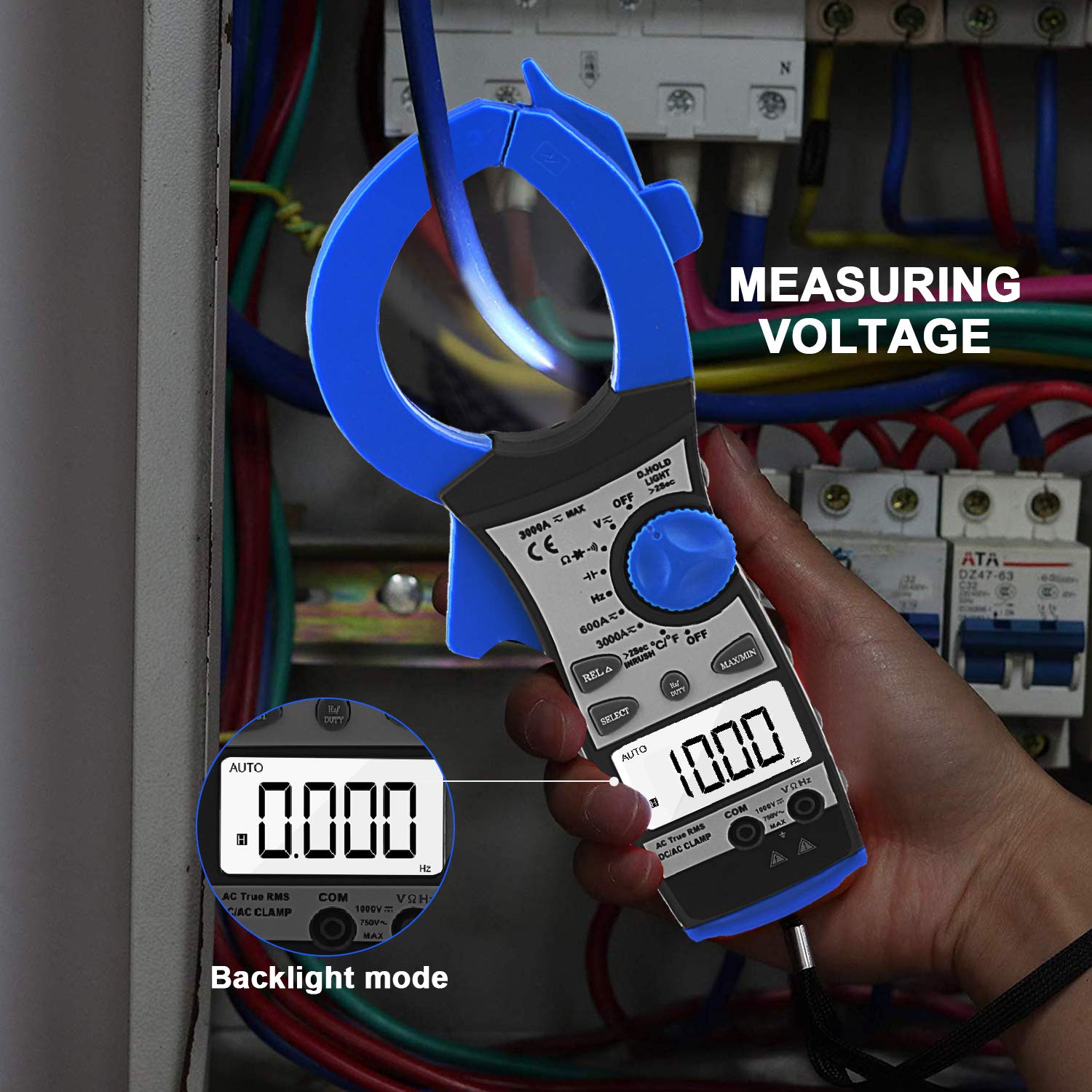
Figure 4.1: Measuring Voltage
This image shows the BT-860N clamp meter being used to measure voltage within an electrical panel. The meter's display is illuminated by its backlight, making the reading visible in a potentially dark environment. An inset shows a close-up of the display in backlight mode.
4.3 AC/DC Current Measurement (Clamp)
The BT-860N supports current measurement up to 3000A. It has two main ranges: 600A and 3000A, with the 3000A range further segmented for precision.
- Turn the rotary switch to the 3000A~ (AC Current) or 3000A- (DC Current) position.
- Open the clamp jaw and enclose only one conductor of the circuit. Ensure the jaw is fully closed.
- Read the current value on the LCD display.

Figure 4.2: AC/DC Current Test
This image depicts the BT-860N clamp meter in use, measuring AC/DC current on a cable within a complex server rack environment. The blue clamp jaw is securely closed around a single conductor, demonstrating the non-contact current measurement capability.
4.4 Resistance Measurement
- Turn the rotary switch to the Ω (Resistance) position.
- Ensure the circuit is de-energized and all capacitors are discharged.
- Connect the test leads across the component to be measured.
- Read the resistance value on the LCD display.
4.5 Frequency Measurement (Hz)
- Turn the rotary switch to the Hz position.
- Connect the test leads to the circuit where frequency is to be measured.
- Read the frequency value on the LCD display.
4.6 Capacitance Measurement
- Turn the rotary switch to the Capacitance position (often shared with diode/continuity).
- Ensure the capacitor is fully discharged before connecting the test leads.
- Connect the test leads across the capacitor terminals.
- Read the capacitance value on the LCD display.
4.7 Temperature Measurement
- Turn the rotary switch to the ℃/℉ (Temperature) position.
- Connect the temperature probe to the COM and T- input jacks.
- Place the tip of the temperature probe on or in the object whose temperature is to be measured.
- Read the temperature value on the LCD display. Use the SELECT button to switch between Celsius and Fahrenheit.

Figure 4.3: Temperature Test
This image illustrates the BT-860N clamp meter performing a temperature measurement. The included temperature probe is submerged in a glass of water, and the meter's display shows the temperature reading.
4.8 Diode Test and Continuity Test
- Turn the rotary switch to the Diode/Continuity position.
- Use the SELECT button to toggle between Diode Test and Continuity Test.
- For Diode Test: Connect the red lead to the anode and the black lead to the cathode. The display shows the forward voltage drop. Reverse the leads to check for open circuit.
- For Continuity Test: Connect the test leads across the circuit or component. A continuous beep indicates continuity (low resistance).
4.9 Special Functions
- HOLD/LIGHT Button: Press once to hold the current reading on the display. Press and hold to activate/deactivate the backlight.
- MAX/MIN Button: Press to enter MAX/MIN mode. The meter will display the maximum or minimum reading recorded since entering the mode. Press again to cycle through MAX, MIN, and current reading.
- RELA (Relative) Button: Used for relative measurement, displaying the difference between the current reading and a stored reference value.
- SELECT Button: Toggles between functions on a shared rotary switch position (e.g., AC/DC current, Diode/Continuity, ℃/℉).
5. Maintenance
5.1 Cleaning
Wipe the meter's case with a damp cloth and mild detergent. Do not use abrasives or solvents. Keep the input terminals clean.
5.2 Battery Replacement
Replace the battery when the low battery indicator appears on the display to ensure accurate readings. Refer to Section 3.1 for instructions.
5.3 Storage
If the meter is not to be used for a long period, remove the battery to prevent leakage and damage to the instrument. Store the meter in a cool, dry place, away from direct sunlight and extreme temperatures.
6. Troubleshooting
| Problem | Possible Cause | Solution |
|---|---|---|
| Meter does not power on. | Dead or incorrectly installed battery. | Check battery polarity or replace battery. |
| "OL" displayed. | Overload or out of range. | Select a higher range or ensure the measured value is within the meter's capabilities. |
| Inaccurate readings. | Low battery, incorrect function/range, or poor test lead connection. | Replace battery, select correct function/range, ensure leads are securely connected. |
| No continuity beep. | Circuit resistance too high. | The beep activates for very low resistance. Check if the circuit is truly continuous. |
7. Specifications
| Parameter | Value |
|---|---|
| Model Number | BT-860N |
| Brand | BTMETER |
| Power Source | Manual (Battery Operated) |
| Style | Digital |
| Item Weight | 370 Grams (13.05 ounces) |
| Package Dimensions | 12.09 x 5.39 x 2.2 inches |
| Color | Black, Blue, Gray, Red |
| Display Digits | 3999 |
7.1 Measurement Ranges and Accuracy
| Measurement | Range | Accuracy | Resolution |
|---|---|---|---|
| DC Current | 0-1000A | 3.0% of rdg + 10 digits | 1A |
| 1000A-2000A | 5.5% of rdg + 20 digits | ||
| 2000A-3000A | 6.5% of rdg + 40 digits | ||
| Overload protection: 3000Arms within 60 seconds | |||
| AC Current | 0-1000A | 3.0% of rdg + 12 digits | 1A |
| 1000A-2000A | 5.5% of rdg + 22 digits | ||
| 2000A-3000A | 6.5% of rdg + 42 digits | ||
| Average sensing, calibrated to RMS of sine wave. Overload protection: 3000Arms within 60 seconds | |||
| DC Voltage | 600mV | 1.0% of rdg + 5 digits | 0.1mV |
| 6V / 60V / 600V | 1.0% of rdg + 5 digits | 1mV / 10mV / 100mV | |
| 1000V | 1.5% of rdg + 5 digits | 1V | |
| Overload protection: 1000V DC / 750Vrms AC. Impedance: 10MΩ. More than 100MΩ on 400mV scale. | |||

Figure 7.1: Factory Testing and Current Specifications
This image shows the BT-860N clamp meter undergoing testing in a factory setting, with various measurement scenarios depicted. Accompanying the images are detailed tables outlining the DC Current and AC Current measurement ranges, accuracy, and resolution, as well as overload protection information.
8. Warranty and Support
BTMETER products are manufactured to high-quality standards and are warranted against defects in materials and workmanship. For specific warranty terms and conditions, please refer to the warranty card included with your product or visit the official BTMETER website.
For technical support, troubleshooting assistance, or service inquiries, please contact BTMETER customer service through the contact information provided on our official website or through your purchase platform. Please have your model number (BT-860N) and purchase details ready when contacting support.


