1. Introduction
This manual provides instructions for the installation and operation of your Bingfu 75 Ohm FM Dipole Antenna and 3-Pin AM Loop Antenna. This antenna set is designed to enhance FM and AM radio reception for compatible stereo systems, including various Sony HiFi Series and Sharp Stereo System models. Proper installation ensures optimal signal quality for your audio experience.
2. Package Contents
Verify that all components are present in your package:
- 1 x 75 Ohm FM Dipole Antenna with F-Type Connector
- 1 x 3-Pin AM Loop Antenna

Image: The complete Bingfu FM Dipole and AM Loop Antenna set, showing both antennas and their connectors.
3. Setup Instructions
Follow these steps to connect your antennas to your stereo receiver:
3.1. Connecting the FM Dipole Antenna
- Locate the FM 75 Ohm UNBAL input terminal on the back of your stereo receiver. This is typically a coaxial F-type connector.
- Connect the F-type connector of the FM Dipole Antenna to this terminal. Ensure a secure connection.
- Extend the two wires of the dipole antenna fully. For optimal reception, position the wires horizontally in a 'T' shape, away from metal objects and other electronic devices. You may use tape or tacks to secure the wires to a wall or furniture.

Image: The FM Dipole Antenna with its wires extended, showing the F-type connector.

Image: A close-up view of the F-type connector on the FM Dipole Antenna.
3.2. Connecting the AM Loop Antenna
- Identify the AM input terminals on your stereo receiver. These are typically two small posts or a 3-pin connector. This antenna uses a 3-pin connector.
- Connect the 3-pin connector of the AM Loop Antenna to the corresponding 3-pin AM input on your receiver. Ensure the pins align correctly.
- Position the AM Loop Antenna upright on a flat surface near your receiver. Rotate the antenna for the best AM signal reception.
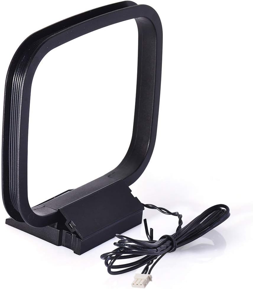
Image: The AM Loop Antenna, designed for upright placement.
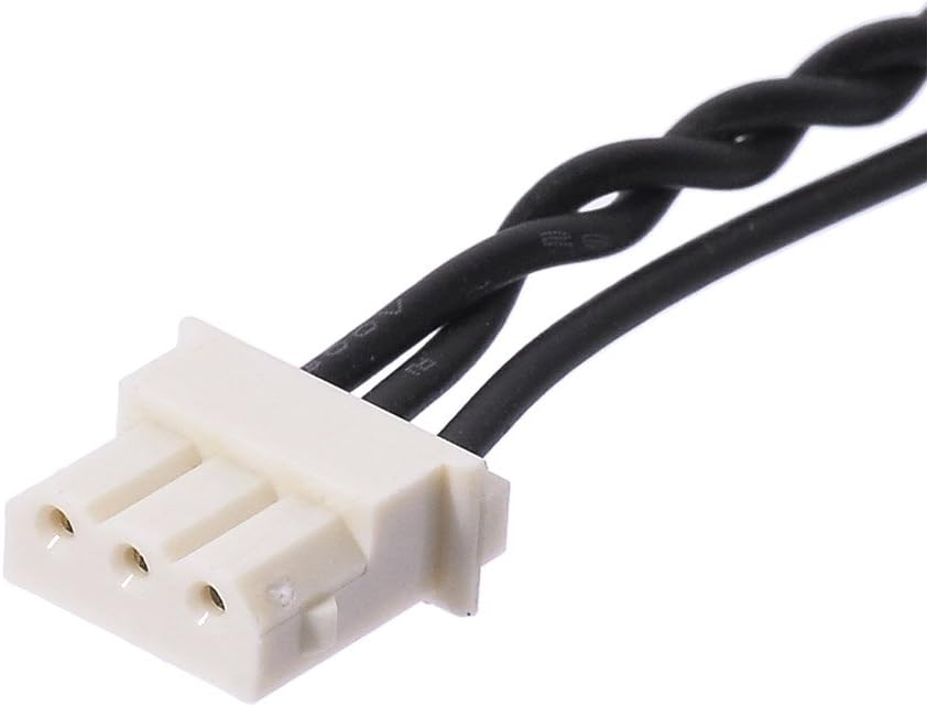
Image: A close-up view of the 3-pin connector on the AM Loop Antenna.
3.3. Connection Diagram
Refer to the diagram below for a visual guide on connecting both antennas to a typical stereo receiver.

Image: Diagram illustrating how to connect the FM Dipole Antenna (F-type) and AM Loop Antenna (3-pin) to the corresponding ports on the back of an audio receiver.
4. Operating Instructions
Once the antennas are connected, power on your stereo receiver and select the FM or AM tuner function. Use the receiver's tuning controls to scan for radio stations. Adjust the position of both the FM dipole wires and the AM loop antenna as needed to achieve the clearest reception for your desired stations.
- For FM reception, experiment with the orientation and extension of the dipole wires. Higher placement often yields better results.
- For AM reception, slowly rotate the AM loop antenna until the signal strength improves and static is minimized.
5. Maintenance
These antennas require minimal maintenance. Keep them clean and dry to ensure longevity and consistent performance.
- Cleaning: Wipe the antennas with a soft, dry cloth. Do not use liquid cleaners or abrasive materials.
- Placement: Avoid placing the antennas in direct sunlight, near heat sources, or in areas with high humidity.
- Cable Care: Ensure antenna cables are not kinked, pinched, or stretched excessively, as this can damage the internal wiring and affect signal quality.
6. Troubleshooting
If you experience poor radio reception, consider the following troubleshooting steps:
| Problem | Possible Cause | Solution |
|---|---|---|
| Weak or no FM signal | Antenna not fully extended or poorly positioned. | Fully extend the FM dipole wires and reposition them. Try different orientations (e.g., horizontal, vertical) and locations. |
| Static or distorted AM signal | AM loop antenna poorly positioned or interference. | Rotate the AM loop antenna slowly to find the optimal orientation. Move it away from other electronic devices that may cause interference. |
| No signal on either band | Loose connection or incorrect input. | Check that both antennas are securely connected to the correct FM and AM input terminals on your receiver. Ensure the receiver is set to the correct tuner mode (FM or AM). |
| Antenna not compatible | Receiver requires different connector types. | Verify your receiver's input types match the antenna connectors (F-type for FM, 3-pin for AM). Consult your receiver's manual if unsure. |
7. Specifications
| Feature | Detail |
|---|---|
| Product Type | FM Dipole Antenna & AM Loop Antenna Set |
| Model Number | BFN00291 |
| FM Antenna Impedance | 75 Ohms (UNBAL) |
| FM Antenna Connector | F-Type Male |
| AM Antenna Connector | 3-Pin Mini Connector |
| Compatible Receivers | Sony STR-ZA5000ES, STR-ZA3100ES, STR-ZA2100ES, STR-ZA110ES, STR-ZA810ES, STR-DH130, STR-DH190, STR-DH550, STR-DH590, STR-DH770, STR-DH790, STR-DN1060, STR-DN1070, STR-DN1080, cmt-eh10, cmt-eh12, cmtfx300i, cmtlx20i, hcdec70, hcdec709ip, hcdec77, hcdec78p, hcdec909ip, hcdec99i, hcdeh10, hcdfx300i, mhc-ec50, mhc-ec55, mhcec609ip, mhc-ec69i, mhc-ec70, mhcec709ip, mhcec77, mhcec78, mhcec79i, mhcec909ip, mhcec98p, mhcec98pi, mhcec99i, mhcgx99. Sharp CD3400, CDC1800, CD-C1800C, CDC2700, CDC2700C, CDC2800, CD-C2800C, CDC3300, CDC3400, CD-C3400C, CDC3700, CDC3800, CDC3800C, CDC401, CDC401C, CDC406, CD-C406C, CDC420, CDC420C, CDC422, CD-C422C, CD-C452, CD-C452C, CDC460, CDC462, CD-C462C, CDC470, CDC472, CMSC640, CD-E67, CMSC660, CPC640, MDX5, SC9730, XL505, XL-S10, XL-30, XL-HP500, CD-BA300. |
| Product Dimensions | 6.69 x 4.72 x 0.51 inches (17 x 12 x 1.3 cm) |
| Item Weight | 2.82 ounces (80 grams) |
| Color | Black, Clear |
8. Warranty Information
Specific warranty details for this product are not provided in this manual. For information regarding warranty coverage, please refer to the product packaging or contact the seller directly. Keep your purchase receipt as proof of purchase.
9. Support
If you require further assistance or have questions not covered in this manual, please contact the seller or manufacturer through their official support channels. You may also visit the BINGFU Store on Amazon for additional product information and contact options.


