
1. Introduction
This manual provides detailed instructions for the installation, operation, and maintenance of the Sensor Switch PP-20 Power Pack. The PP-20 is a robust power pack designed for relay circuit protection, capable of powering up to 14 sensors. It supports 120V, 240V, and 277V AC electrical systems.
Please read this manual thoroughly before installation and operation to ensure safe and efficient use of the device.
2. Product Features
The Sensor Switch PP-20 Power Pack offers the following key features:
- Type: Power Pack
- Material: Durable Plastic construction
- Color: Black finish
- Voltage Compatibility: Supports 120V, 240V, and 277V AC
- Mounting: Designed for fixture mounting
- Sensor Capacity: Capable of powering up to 14 sensors
- Function: Provides relay circuit protection
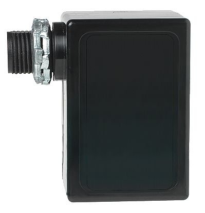
Figure 2.1: Side view of the Sensor Switch PP-20 Power Pack, illustrating its compact black plastic housing and the threaded conduit connection for installation.
3. Setup and Installation
Proper installation is crucial for the safe and effective operation of the PP-20 Power Pack. It is recommended that installation be performed by a qualified electrician in accordance with all local and national electrical codes.
3.1. Safety Precautions
- Always disconnect power at the circuit breaker before installing or servicing the device.
- Verify voltage compatibility (120V, 240V, or 277V AC) before connecting.
- Do not exceed the maximum current rating of 20 AMP.
- Ensure all connections are secure and properly insulated.
3.2. Mounting
The PP-20 Power Pack is designed for fixture mounting. Secure the device firmly to a suitable electrical box or fixture using appropriate hardware (not included).
3.3. Wiring Diagram (Conceptual)
While a specific wiring diagram is not provided in this manual, the PP-20 typically connects to line voltage, neutral, and provides low-voltage power to sensors and a switched output for lighting loads. Refer to the wiring diagram supplied with your specific sensor and lighting system for detailed connection instructions. Ensure proper grounding.
Note: For detailed wiring instructions, consult the product's packaging or the manufacturer's official website.
4. Operation
Once properly installed and powered, the PP-20 Power Pack operates by providing the necessary power to connected low-voltage sensors (e.g., occupancy sensors, photocells) and switching line voltage to lighting fixtures based on the sensor's input.
- Power Indicator: Some models may feature an LED indicator to show power status.
- Sensor Integration: The power pack acts as an interface between line voltage and low-voltage control devices.
- Relay Function: The internal relay switches the connected load (e.g., lights) on or off based on signals received from the sensors.
The operation is largely automatic once the sensors are configured. Refer to the sensor's manual for specific configuration and adjustment procedures.
5. Maintenance
The Sensor Switch PP-20 Power Pack is designed for minimal maintenance. However, periodic checks can ensure continued reliable operation.
- Cleaning: If necessary, gently wipe the exterior of the unit with a dry, soft cloth. Do not use abrasive cleaners or solvents.
- Connection Check: Periodically inspect wiring connections for tightness and signs of wear or corrosion. Ensure power is disconnected before inspection.
- Environmental Conditions: Ensure the operating environment remains within the specified temperature and humidity ranges to prevent damage.
No user-serviceable parts are inside the unit. Do not attempt to open or repair the power pack.
6. Troubleshooting
If you encounter issues with your PP-20 Power Pack, consider the following common troubleshooting steps:
| Problem | Possible Cause | Solution |
|---|---|---|
| No power to sensors/load |
|
|
| Load (lights) not switching |
|
|
If the problem persists after attempting these solutions, contact Sensor Switch technical support.
7. Specifications
| Attribute | Detail |
|---|---|
| Model Number | PP-20 |
| Part Number | 745975809592 |
| Type | Power Pack |
| Voltage AC | 120V, 240V, 277V |
| Max Current | 20 AMP |
| Sensor Capacity | Up to 14 sensors |
| Mounting | Fixture |
| Color | Black |
| Material | Plastic |
| Dimensions (Approx.) | 2 x 2 x 2 inches |
| Weight (Approx.) | 1.01 Pounds |
| Manufacturer | PER - Sensor Switch |
| First Available Date | November 16, 2018 |
8. Warranty and Support
For warranty information and technical support, please contact Sensor Switch directly. Keep your purchase receipt as proof of purchase.
Manufacturer: PER - Sensor Switch
For the most up-to-date support information, visit the official Sensor Switch website or contact their customer service department.
