BANNER ENGINEERING S18AW3FF50
S18AW3FF50 EZ-Beam S18 Series Photoelectric Sensor User Manual
Model: S18AW3FF50 | Brand: BANNER ENGINEERING
1. Introduction
This manual provides essential information for the installation, operation, and maintenance of the BANNER ENGINEERING S18AW3FF50 EZ-Beam S18 Series Photoelectric Sensor. This sensor is designed for reliable object detection in industrial environments, featuring a 50 mm range, 20-250VAC input, and SPST solid-state light operate output.
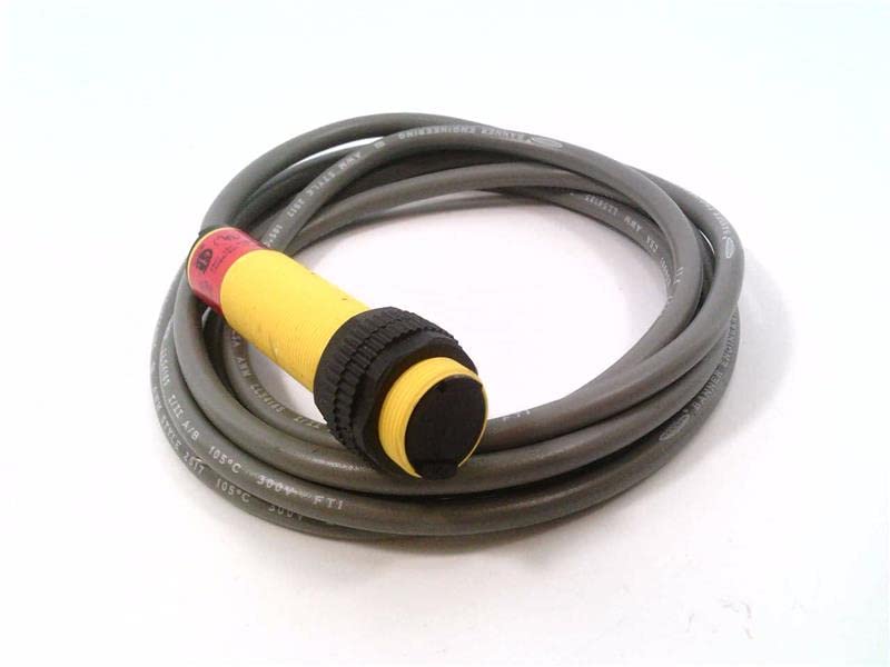
Figure 1: BANNER ENGINEERING S18AW3FF50 Photoelectric Sensor with coiled cable.
2. Setup and Installation
Proper installation is crucial for optimal performance and safety. Follow these steps carefully.
2.1 Unpacking and Inspection
- Carefully remove the sensor from its packaging.
- Inspect the sensor for any visible damage that may have occurred during shipping.
- Verify that all components listed in the packing slip are present.
2.2 Mounting the Sensor
The S18AW3FF50 sensor is designed for easy mounting. Ensure the mounting surface is stable and free from excessive vibration.
- Select a mounting location that provides clear line-of-sight for the sensor's detection range (50 mm).
- Secure the sensor using appropriate mounting hardware (not included). The sensor features a threaded barrel for secure attachment.
- Ensure the sensor is oriented correctly for the intended detection application.
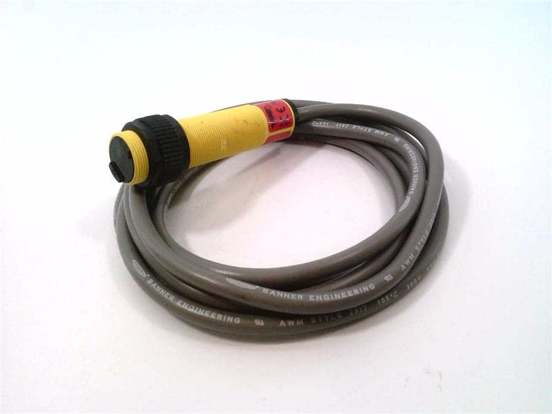
Figure 2: Side view of the S18AW3FF50 sensor, showing the threaded barrel and cable.
2.3 Electrical Connections
WARNING: Disconnect all power before making electrical connections to prevent electric shock or damage to the equipment.
The S18AW3FF50 operates on 20-250VAC input and provides an SPST Solid-State Light Operate output. The sensor comes with a 2M (6.5FT) cable.
| Wire Color | Function |
|---|---|
| Brown | AC Line (L1) |
| Blue | AC Neutral (L2) |
| Black | Output (SPST Light Operate) |
Connect the sensor wires to the control circuit according to the provided wiring diagram and local electrical codes. Ensure all connections are secure.
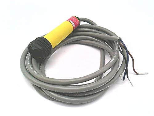
Figure 3: S18AW3FF50 sensor showing the cable with exposed wires for electrical connection.
3. Operation
Once installed and wired, the S18AW3FF50 sensor is ready for operation.
3.1 Powering On
Apply power to the sensor (20-250VAC). The sensor will typically have an indicator LED (if present) to show power status and output state.
3.2 Detection Principle
The S18AW3FF50 is a photoelectric sensor operating in a fixed field mode. It emits a light beam and detects objects based on the reflection or interruption of this beam. The "Light Operate" output means the output will be active when light is received by the sensor (i.e., when an object is detected or not detected, depending on the specific fixed field configuration).
3.3 Range and Performance
The sensor has a specified detection range of 50 mm. Ensure that objects to be detected fall within this range for reliable operation. Environmental factors such as dust, moisture, and ambient light can affect performance.
4. Maintenance
The S18AW3FF50 sensor is designed for low maintenance. Regular checks can ensure long-term reliable operation.
4.1 Cleaning
- Periodically clean the sensor lens and housing to remove dust, dirt, or debris that may accumulate and interfere with detection.
- Use a soft, lint-free cloth and a mild cleaning solution if necessary. Avoid abrasive cleaners or solvents.
4.2 Cable and Connection Inspection
- Regularly inspect the sensor cable for any signs of wear, cuts, or damage.
- Check electrical connections to ensure they remain secure and free from corrosion.
5. Troubleshooting
This section provides solutions to common issues encountered with the S18AW3FF50 sensor.
| Problem | Possible Cause | Solution |
|---|---|---|
| Sensor not powering on | No power supply; Incorrect wiring; Damaged sensor. | Verify power supply (20-250VAC); Check wiring against Table 1; Replace sensor if damaged. |
| Sensor not detecting objects | Object out of range (50 mm); Dirty lens; Misalignment; Ambient light interference. | Ensure object is within 50 mm range; Clean sensor lens; Realign sensor; Shield sensor from strong ambient light. |
| Intermittent detection | Vibration; Loose connections; Fluctuating power. | Secure sensor mounting; Check all electrical connections; Ensure stable power supply. |
6. Specifications
Key technical specifications for the BANNER ENGINEERING S18AW3FF50 Photoelectric Sensor.
- Model: S18AW3FF50
- Series: EZ-Beam S18 Series
- Detection Range: 50 mm
- Input Voltage: 20-250VAC
- Output Type: SPST Solid-State Light Operate
- Cable Length: 2M (6.5FT)
- Sensor Type: Photoelectric, Fixed Field
- Manufacturer: BANNER ENGINEERING
- ASIN: B07RZTBRLS
- Date First Available: December 3, 2021
7. Warranty and Support
For warranty information and technical support, please contact BANNER ENGINEERING directly or refer to their official website.
Return Policy: The product may be subject to a return policy of 30 days for refund/replacement, as per the seller's terms.
Manufacturer: BANNER ENGINEERING
For further assistance, visit the BANNER ENGINEERING official website.
Related Documents - S18AW3FF50
 |
Understanding Light Operate and Dark Operate Sensor Modes | Banner Engineering Banner Engineering's iKnow Training Note explains the operational principles of Light Operate (LO) and Dark Operate (DO) modes for photoelectric sensors, detailing Opposed, Retroreflective, and Proximity sensing configurations. |
 |
Banner S18 Series AC Voltage Sensors: Installation Guide and Specifications Comprehensive guide to Banner Engineering's S18 Series AC Voltage sensors, covering installation, models, wiring, dimensions, specifications, and accessories. Features detailed technical data for various sensing modes including opposed, retro-reflective, polarized retro-reflective, and diffuse. |
 |
R45C Modbus to Dual Analog Input-Output Converter Quick Start Guide Quick start guide for the Banner Engineering R45C Modbus to Dual Analog Input-Output Converter, detailing features, installation, status indicators, specifications, and warranty information. |
 |
Banner Engineering Sensor Solutions Overview A comprehensive guide to Banner Engineering's range of industrial sensors, including photoelectric, laser, ultrasonic, radar, light curtains, and vision sensors. Features selection criteria and technical specifications. |
 |
Q5Z Global Laser Measurement Sensor with IO-Link Instruction Manual Comprehensive instruction manual for the Banner Engineering Q5Z Global Laser Measurement Sensor with IO-Link, detailing its features, configuration options, installation procedures, specifications, and support. |
 |
Banner QS30AF Adjustable Field Sensor Series Detailed information on the Banner QS30AF series of adjustable field sensors, including features, specifications, operating principles, configuration, and accessories. This document covers optical triangulation, sensor setup (background suppression, object detection, dynamic configuration), remote configuration, indicator functions, wiring, installation notes, performance curves, dimensions, and warranty information. |
Ask a question about this manual
Ask about setup, troubleshooting, compatibility, parts, safety, or missing instructions. Manuals+ will review the question and use this page’s manual context to help answer it.